Lincoln Navigator: Instrument Panel and Console / Instrument Panel. Removal and Installation
Special Tool(s) /
General Equipment
Removal
NOTE:
Removal steps in this procedure may contain installation details.
All vehicles
-
Remove both front seats.
Refer to: Front Seat (501-10A Front Seats, Removal and Installation).
-
Depower the SRS .
Refer to: Supplemental Restraint System (SRS) Depowering (501-20B Supplemental Restraint System, General Procedures).
-
Remove the front floor console.
Refer to: Floor Console (501-12 Instrument Panel and Console, Removal and Installation).
-
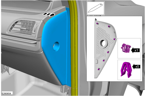
Release the clips and remove the LH instrument panel finish panel.
Use the General Equipment: Interior Trim Remover
-
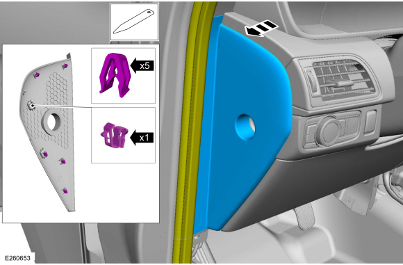
Release the clips and remove the RH instrument panel finish panel.
Use the General Equipment: Interior Trim Remover
-
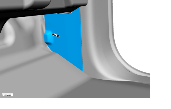
Remove the lower RH access door.
-
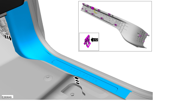
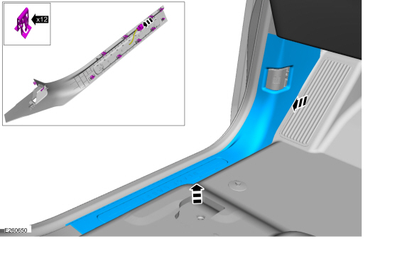
Release the clips and remvoe the RH scuff plate.
-
Release the clips and remove the LH scuff plate.
-
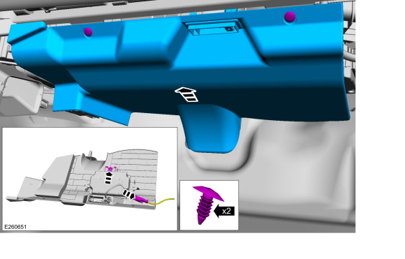
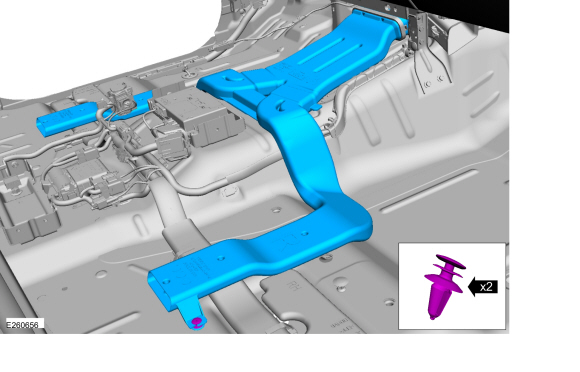
Remove the push pins and remove the RH insulation panel.
-
Disconnect the electical connector.
-
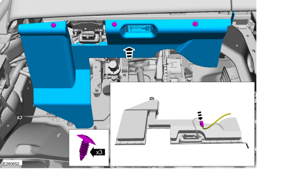
Remove the push pins and remove the LH insulation panel.
-
Disconnect the electical connector.
-
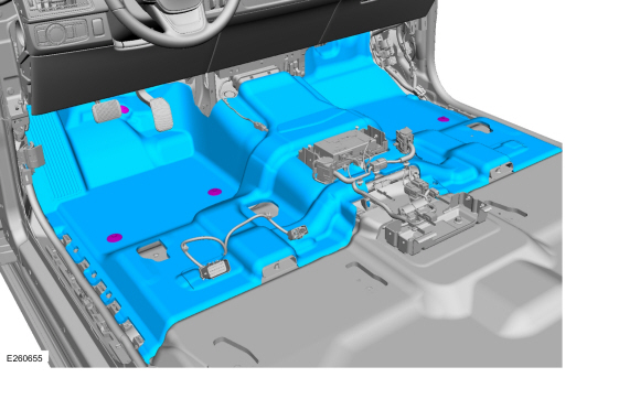
Release the front floor covering retainers and remove the front floor covering.
-
Remove the rear HVAC duct retainers and remove the duct.
-
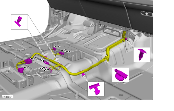
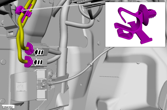
Disconnect the electrical connectors, detach the harenss retainers and position the harness aside.
-
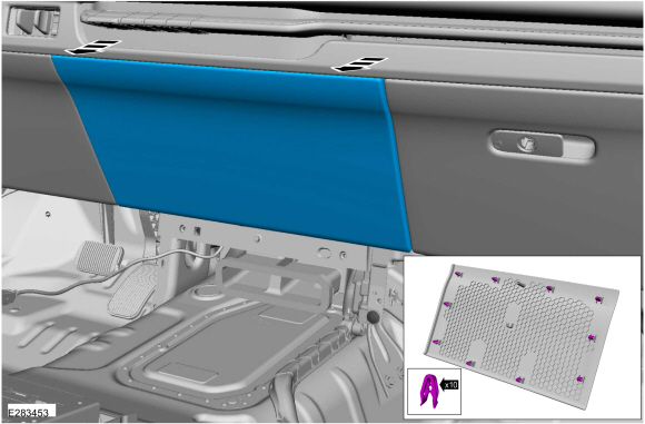
Release the clips and remove the trim panel.
-
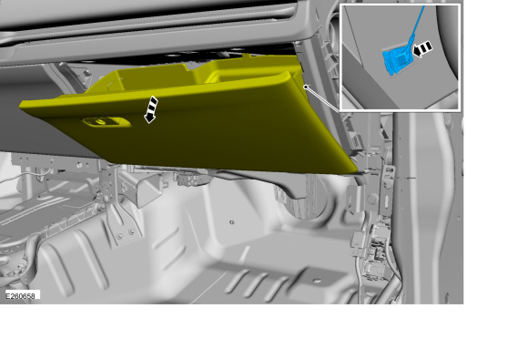
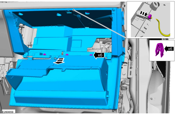
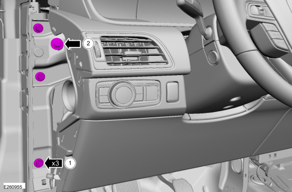
Open the glove compartment door and remove the check strap.
-
Remove the bolts, release the clips and remove the glove compartment.
-
Disconnect the electrical connector.
Torque:
25 lb.in (2.8 Nm)
-
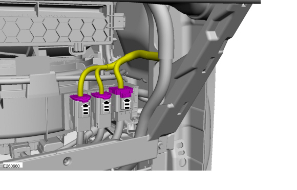
Disconnect the electrical connectors in the RH glove compartment opening.
-
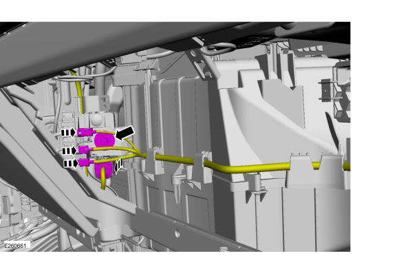
Disconnect the electrical connectors and remove the bolt in the LH glove compartment opening.
-
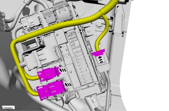
Disconnect the lower RH instrument panel electrical connectors.
-
NOTE:
Located in the lower LH cowl area.
Disconnect the electrical connectors and detach the harness retainer.
-
Remove the defrost vent trim panel.
Refer to: Defrost Vent Trim Panel (501-12 Instrument Panel and Console, Removal and Installation).
Vehicles with HUD (Heads Up Display)
-
Remove the steering column.
Refer to: Steering Column - Remove for Access (211-04 Steering Column, Removal and Installation).
-
NOTE:
Bolts accessed above the steering steering column.
Remove the bolts.
Torque:
155 lb.in (17.5 Nm)
Vehicles without HUD (Heads Up Display)
-
NOTE:
Do not allow the steering wheel to rotate while
the steering column shaft is disconnected for damage to the clockspring
may result.
Secure the steering wheel.
-
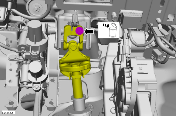
 WARNING:
Install a new steering column shaft bolt. Reuse
could result in bolt failure and loss of vehicle control. Failure to
follow this instruction may result in serious injury to vehicle
occupant(s).
WARNING:
Install a new steering column shaft bolt. Reuse
could result in bolt failure and loss of vehicle control. Failure to
follow this instruction may result in serious injury to vehicle
occupant(s).
Remove and discard the bolt and disconnect the upper steering column shaft.
Torque:
15 lb.ft (21 Nm)
-
Remove the LH upper instrument panel bolts.
Torque:
18 lb.ft (25 Nm)
All vehicles
-
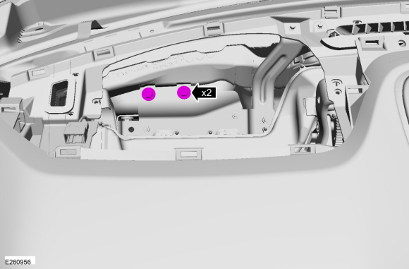
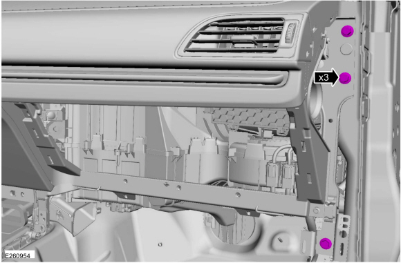
Remove the RH upper instrument panel bolts.
Torque:
18 lb.ft (25 Nm)
-
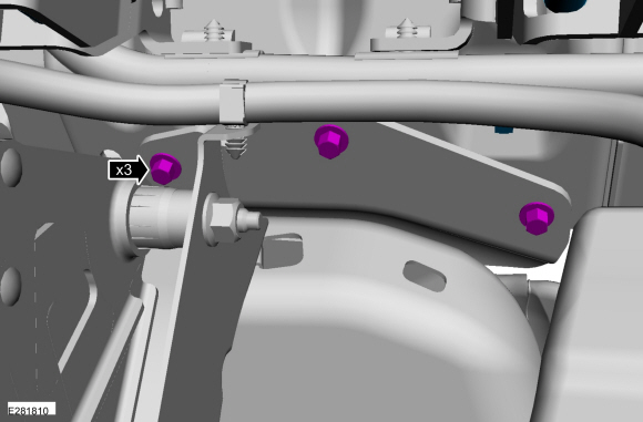
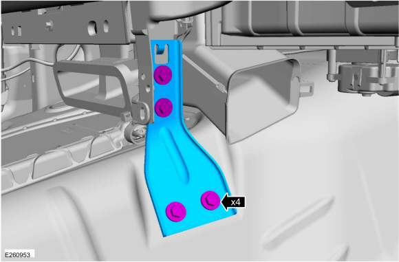
Remove the RH instrument panel center support bolts and bracket.
Torque:
80 lb.in (9 Nm)
-
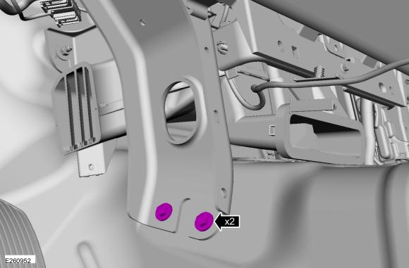
Remove the LH instrument panel center support bolts
Torque:
80 lb.in (9 Nm)
-
NOTE:
Leave one bolt finger tight to hold the instrument panel prior to removal.
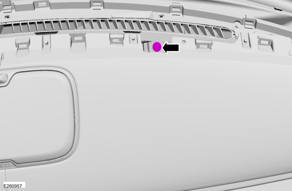
-
Remove the bolt.
Torque:
18 lb.ft (25 Nm)
-
Remove the bolt.
Torque:
18 lb.ft (25 Nm)
-
NOTE:
Leave one bolt finger tight to hold the instrument panel prior to removal.
Remove the bolts.
Torque:
18 lb.ft (25 Nm)
-
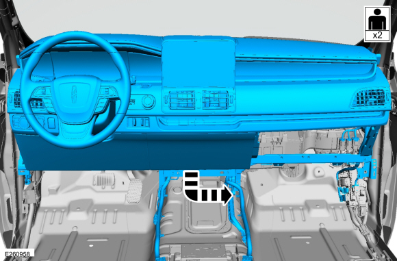
NOTE:
To avoid damaging the instrument panel, an assistant is required when carrying out this step.
NOTE:
Make sure not to damage the instrument panel when remove the instrument panel from the vehicle.
NOTE:
Make sure that all electrical connectors and
wiring are not hindered before removing the instrument panel or damage
to the components may occur.
Rotate the instrument panel face down and remove through the RH front door opening.
Installation
All vehicles
-
To install, reverse the removal procedure.
-
Repower the SRS .
Refer to: Supplemental Restraint System (SRS) Repowering (501-20B Supplemental Restraint System, General Procedures).
Vehicles with HUD (Heads Up Display)
-
Install the steering column.
Refer to: Steering Column - Install after Access (211-04 Steering Column, Removal and Installation).
All vehicles
-
NOTE:
Anytime the parking brake switch electrical connector has been
disconnected, the EPB system is deactivated and a DTC is stored in the
ABS module. Perform the following step to restore the EPB system and
clear the ABS module DTC .
Apply and release the parking brake twice within 5
seconds, pausing with the switch in the NEUTRAL position for
approximately one-half second between each apply and release. Using a
diagnostic scan tool, clear the EPB module DTC .
Special Tool(s) /
General Equipment
Interior Trim Remover
Removal
NOTE:
Removal steps in this procedure may contain installation details...
Special Tool(s) /
General Equipment
Interior Trim Remover
Removal
NOTE:
Removal steps in this procedure may contain installation details...
Other information:
Shift Point Road Test
NOTE:
Always drive the vehicle in a safe manner according to driving conditions and obey all traffic laws.
Upshift Gear Sequence
At times the 10-speed transmission may skip gears when the vehicle starts from a complete stop...
Removal
NOTE:
Removal steps in this procedure may contain installation details.
NOTE:
LH (left-hand) rear lamp assembly shown, RH (right-hand) rear lamp assembly simlar.
Remove the rear bumper cover.
Refer to: Rear Bumper Cover (501-19 Bumpers, Removal and Installation)...
 Glove Compartment. Removal and Installation
 Instrument Panel Center Finish Panel. Removal and Installation