Lincoln Navigator: Engine Ignition - 3.5L EcoBoost (272kW/370PS) / Ignition Coil-On-Plug. Removal and Installation
Removal
Both sides
-
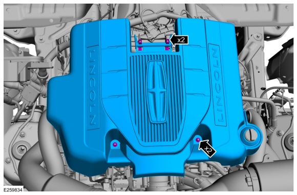
Remove the engine appearance cover retainers,
release the engine appearance cover from the rear retainers and then
remove the engine appearance cover.
 |
Left side
-
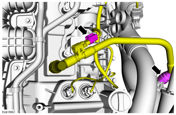
Disconnect the electrical connector, then disconnect
the crankcase ventilation tube and move it out of the way.
Refer to: Quick Release Coupling (310-00 Fuel System - General Information - 3.5L EcoBoost (272kW/370PS)) .
 |
Both sides
-
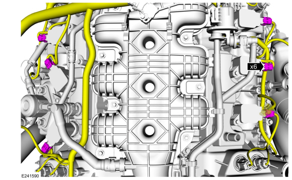
Disconnect the ignition coil-on-plug electrical connectors.
 |
-
NOTE: Use compressed air to remove any foreign material from the ignition coil-on-plugs and surrounding area before removing the ignition coil-on-plugs.
NOTE: When removing the ignition coil-on-plugs, a slight twisting motion will break the seal and ease removal.
-
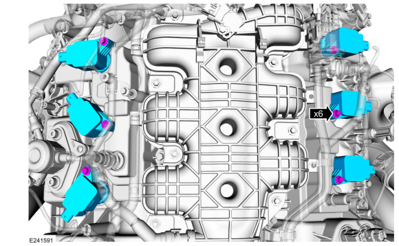
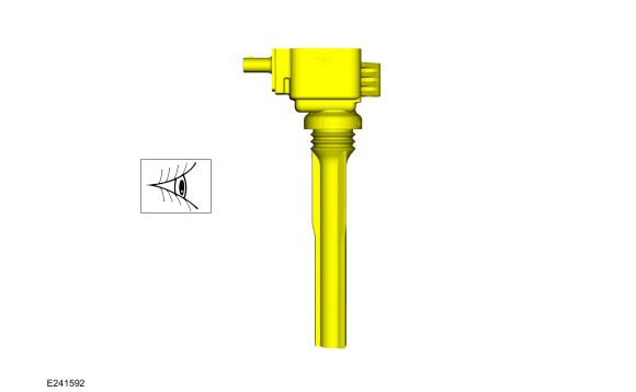
Remove the ignition coil-on-plug retainers.
-
Remove the ignition coil-on-plugs.
-
Remove the ignition coil-on-plug retainers.
 |
Installation
Both sides
-
Inspect the ignition coil-on-plugs. Replace any
damaged ignition coil-on-plugs. Replace any of the ignition coil-on-plug
boots with cracks, rips or tears.
 |
-
-
Install the ignition coil-on-plugs.
-
Install and tighten the ignition coil-on-plug retainers.
Torque:
Stage 1: 62 lb.in (7 Nm)
Stage 2: 50°
-
Install the ignition coil-on-plugs.
|
-
Connect the ignition coil-on-plug electrical connectors.
|
Left side
-
Connect the crankcase ventilation tube, then connect the electrical connector.
Refer to: Quick Release Coupling (310-00 Fuel System - General Information - 3.5L EcoBoost (272kW/370PS)) .
|
Both sides
-
Install the engine appearance cover into the rear
retainers, then install and tighten the engine appearance cover
retainers.
Torque: 97 lb.in (11 Nm)
|
 Engine Ignition. Diagnosis and Testing
Diagnostic Trouble Code (DTC) Chart
Diagnostics in this manual assume a certain skill level and knowledge of Ford-specific diagnostic practices. REFER to: Diagnostic Methods (100-00 General Information, Description and Operation)...
 Spark Plugs. Removal and Installation
Removal
Remove the ignition coil-on-plugs.
Refer to: Ignition Coil-On-Plug (303-07 Engine Ignition - 3.5L EcoBoost (272kW/370PS), Removal and Installation)...
Other information:
Lincoln Navigator 2018-2026 Workshop Manual: Exhaust Manifold Cleaning and Inspection. General Procedures
Special Tool(s) / General Equipment Feeler Gauge Cleaning Clean the exhaust manifold using a suitable solvent. Use a plastic scraping tool to clean the gasket sealing surfaces. Inspection NOTE: New exhaust manifold gaskets, studs, nuts and/or bolts must be installed when an exhaust manifold is serviced...
Lincoln Navigator 2018-2026 Workshop Manual: Finish Panel Repair. General Procedures
Repair NOTE: Mouldings located on the front and rear window frames may experience minor scratches from vehicle shipment or car wash racks. The imperfections may be repaired instead of replacing components by following the steps below. NOTE: Scratches deep enough to cause a thumb nail to catch cannot be repaired and the component must be replaced...
Categories
- Manuals Home
- 4th Gen Lincoln Navigator Service Manual (2018 - 2026)
- Body Control Module (BCM). Removal and Installation
- Identification Codes. Description and Operation
- Head Up Display (HUD) Module Calibration. General Procedures
- Body and Paint
- Rear View Mirrors - System Operation and Component Description. Description and Operation
Differential Case Runout Check. General Procedures
Special Tool(s) / General Equipment
 205-1016
Installer, Differential Bearing
TKIT-2014D-ROW2
TKIT-2014D-FL_ROW
 205-153
(T80T-4000-W)
205-153
(T80T-4000-W)
Handle
 205-D061
(D83T-4205-C2)
205-D061
(D83T-4205-C2)
Step Plate Dial Indicator Three Leg Puller Punch