Lincoln Navigator: Automatic Transmission External Controls / External Controls - System Operation and Component Description. Description and Operation
System Diagram
E339845 *.sttxt { visibility: hidden; } *.stcallout { visibility: visible; } 1 Drive Door Latch #1 2 GSM 3 Drive Door Latch #2 4 GWM 5 BCM 6 Brake On/Off (BOO) Switch 7 Brake Pressure Switch (BPS) 8 PCM 9 IPC 10 RCM PT-CAN HS2-CAN HS2-CAN HS2-CAN HS3-CAN HS-CAN-FD HS-CAN-FD 11 ABS Module| Item | Description |
|---|---|
| 1 | Drive Door Latch #1 |
| 2 | GSM |
| 3 | Drive Door Latch #2 |
| 4 | GWM |
| 5 | BCM |
| 6 | Brake On/Off (BOO) Switch |
| 7 | Brake Pressure Switch (BPS) |
| 8 | PCM |
| 9 | IPC |
| 10 | RCM |
| 11 | ABS Module |
Network Message Chart
| Broadcast Message | Originating Module | Message Purpose |
|---|---|---|
| Brake switch position | BCM | Input from brake switch necessary to change gears. |
| Gear data | GSM | Message sent to PCM which gear is commanded. |
| Gear confirmation | PCM | Input to GSM confirming gear selection. |
| PRND mode | IPC | Used for PRND display. |
| Gear command | PCM | Input to change gears. |
| Key in ignition status | BCM | Input used to change gears. |
| Vehicle lock status | BCM | Input used to move transmission out of P . |
| Seat belt buckle data | RCM | Input from seat belt buckle to determine driver presence. |
System Operation
Component Description
When the driver needs to change gear position the driver selects P R N or D by pressing buttons on a GSM . The GSM senses the pressed button and sends a request over the Subnet Network, and the High Speed Controller Area Network 2 (HS2-CAN) through the GWM over the High Speed Controller Area Network 1 (HS1-CAN) to the PCM . The PCM receives the input from the GSM , combines in vehicle conditions and moves the transmission to the commanded position. The PCM reads the transmission range sensor (TRS) and confirms the correct position has been achieved.
There is a redundant Transmission Controller Area Network (TRANS-CAN) that allows the GSM to communicate directly with the PCM in the event of a malfunction in the HS1-CAN, the HS2-CAN or the GWM .
GSM
Each GSM button has three individual switch contacts that are used as input that the button has been pressed. If one switch contact is seen as nonfunctional the system will still work properly. However, if two switch contacts fail the button is no longer deemed reliable and a fault message is displayed. When park is selected above 5 mph neutral is provided along with a message in the IPC . The Brake Transmission Shift Interlock (BTSI) CAN signal is used for normal function to shift from P .
PCM
The PCM actuates the transmission in place of a conventional selector lever and selector lever cable. It receives commands from the GSM via High Speed CAN .
IPC
The IPC receives signals from the PCM and displays the current range of the transmission on the PRND. Under some circumstances messages from the shift by wire system are also displayed for the customer on the multifunction display. For example, "Press Brake to shift from Park" is displayed when an attempt to shift to a non-park rotary dial position while the vehicle is in P and the brake is not pressed.
BCM
The BCM provides Brake Transmission Shift Interlock (BTSI) information, GSM LED intensity status, electronic door lock commands, and ignition status to the GSM and PCM . The BCM is also responsible for customizing BTSI and other signals based on local regulations and vehicle features.
Push Button Shift Modes
Automatic Return to Park
NOTE: This feature does not operate when your vehicle is in Stay In Neutral Mode or neutral tow.
NOTE: This feature may not work properly if the door ajar switch is malfunctioning.
The vehicle has a safety feature that will automatically shift the transmission into P when one of the following conditions are met at low speed:
- The ignition is turned off and vehicle falls below low speed threshold
- The driver door is opened with the seat belt unlatched
- The driver seat belt is unlatched while the driver door is open
If the vehicle is turned off while moving, the transmission will first shift into N until it comes to a complete stop and then will shift into P automatically.
SelectShift™ Mode
To enter SelectShift™ mode, first select D on the GSM . The SelectShift™ mode is activated by pressing the upshift and downshift paddle switches on the steering wheel.
Stay in Neutral Mode
If necessary for the vehicle to stay in N without the driver present, such as being pulled through a car wash, this mode disables Return to Park. In Stay in Neutral the system will remain awake draining the battery if the engine is off. When you enter neutral at low speed a message will be displayed stating press the N button again to stay in neutral mode. Then, if the driver presses the N button within the time limit, the message Stay in Neutral Mode appears on the multifunction display. During this mode the N position on the GSM flashes continuously and the instrument cluster will display N as the selected gear. To exit the Stay in Neutral Mode, shift out of neutral.
Neutral Tow Mode
Refer to: Emergency Park Position Release (307-05 Automatic Transmission External Controls, General Procedures).
for information on moving the transmission into N with the engine off or with a vehicle that will not crank.
Adaptive Tow/Haul
On vehicles equipped with Adaptive Tow/Haul, the PCM determines if Tow/Haul is needed through a vehicle mass calculation. The vehicle mass calculation relies heavily on longitudinal acceleration information from the ABS module to determine if a trailer is connected and if that trailer is heavy enough to require the Tow/Haul function.
In order for the PCM to accurately calculate vehicle mass, the vehicle must be driven in a straight line (0 Yaw Rate), moving forward and with adequate acceleration. Once these conditions are met, the PCM begins calculating vehicle mass, which takes a minimum of five minutes to complete. This calculation becomes faster and more accurate over time as the PCM is able to use historical data to learn the vehicle mass and calculate changes to the mass more quickly.
If the PCM calculates a large enough increase in vehicle mass, Tow/Haul is enabled and the Tow/Haul indicator is illuminated. Since the vehicle must be driven in order for this calculation to take place, the Tow/Haul indicator will not be illuminated as soon as a trailer is connected, and not all trailers are heavy enough to require the Tow/Haul function.
Park by Wire
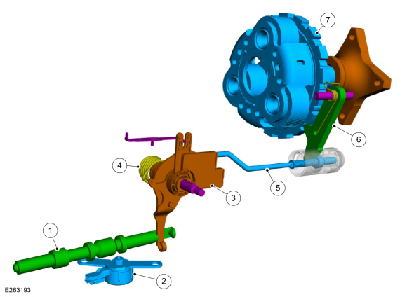
| Item | Description |
| 1 | Park Lock Pawl Valve |
| 2 | Park Lock Pawl Solenoid |
| 3 | TR Sensor |
| 4 | Park Return Spring |
| 5 | Park Pawl Actuator rod |
| 6 | Park Pawl |
| 7 | Output Shaft and Planetary Carrier |
Park by Wire
- Uses a GSM with push buttons in place of a mechanical shifter as the customer interface for selecting (P, R, N, D, M).
-
The transmission hydraulic controls are modified
using a park lock pawl valve connected to the park rod which unlocks
and locks the parking pawl from the carrier.
- Uses clutch B and D hydraulic pressure to push the system out of Park.
- Once out of Park, clutches A, B, C, D or F can continue to hold the system out of Park.
- A park lock pawl solenoid is used to allow the system to remain out of Park when the engine is not running.
- The dual TR sensors indicate the state of the Park system and are not used to determine customer selected range, which is now provided by the GSM .
- A mechanical P override has been provided for in-plant use and towing. This consists of a lever on the side of the transmission that can be bolted into one of 2 positions, normal operating position or park override position. In the override position the park lock pawl valve is held in the applied position to keep the parking pawl unlocked from the carrier.
Park Override Lever

| Item | Description |
|---|---|
| 1 | Park override lever in the normal operating position |
| 2 | Park override lever in the park override position |
 External Controls - Overview. Description and Operation
The shift by wire system uses a push button GSM which interfaces with the PCM to select gear positions.
The shift by wire system also includes a brake shift interlock that
will not allow the transmission to shift out of P unless the brake pedal
is applied...
 External Controls. Diagnosis and Testing
Inspection and Verification
Diagnostics in this manual assume a certain skill level and knowledge of Ford-specific diagnostic practices. REFER to: Diagnostic Methods (100-00 General Information, Description and Operation)...
Other information:
Lincoln Navigator 2018-2026 Workshop Manual: Rear Drive Axle and Differential. Description and Operation
The 9.75-inch ring gear rear conventional differential has 3.31 and 3.73 gear ratio versions. The 9.75-inch ring gear rear differential with eLSD has 3.73 gear ratio. Rear Drive Axle and Differential The rear axle assembly consists of the following: Integral-type housing hypoid gear design (center of the pinion set below the centerline of the ring gear) Hypoid differentia..
Lincoln Navigator 2018-2026 Workshop Manual: Variable Camshaft Timing (VCT) System. Diagnosis and Testing
Diagnostic Trouble Code (DTC) Chart Diagnostics in this manual assume a certain skill level and knowledge of Ford-specific diagnostic practices. REFER to: Diagnostic Methods (100-00 General Information, Description and Operation). Module DTC Description Action PCM P0010:00 'A' Camshaft Position Actuator 'A' Control Circuit/Open Bank 1: No Sub Type Information GO to..
Categories
- Manuals Home
- 4th Gen Lincoln Navigator Service Manual (2018 - 2026)
- Front Bumper Cover. Removal and Installation
- Rear Bumper. Removal and Installation
- Liftgate Trim Panel. Removal and Installation
- All Terrain Control Module (ATCM). Removal and Installation
- SYNC Module [APIM]. Removal and Installation
Wheel to Hub Runout Minimization. General Procedures
Check
NOTE: Wheel-to-hub optimization is important. Clearance between the wheel and hub can be used to offset or neutralize the Road Force® or run-out of the wheel and tire assembly. For every 0.001 inch of wheel-to-hub clearance, the Road Force® can be affected between 1 and 3 pounds depending on the tire stiffness.
NOTE: The example below illustrates how the clearance between the wheel and the hub can be used to offset the high spot of radial run-out or Road Force®. Following the procedure will make sure of the best optimization.
Position the wheel and tire assembly on the vehicle so that the high spot location of radial run-out or Road Force® is at the 6 o'clock position and