Lincoln Navigator: Ethernet Module Communications Network / Ethernet Module Communications Network. Diagnosis and Testing
Diagnostic Trouble Code (DTC) Chart
Diagnostics in this manual assume a certain skill level and knowledge of Ford-specific diagnostic practices.
REFER to: Diagnostic Methods (100-00 General Information, Description and Operation).
| Module | DTC | Description | Action |
|---|---|---|---|
| APIM | U2400:81 | Ethernet Failure With Gateway Module A (GWM): Invalid Serial Data Received | GO to Pinpoint Test A |
| APIM | U2400:92 | Ethernet Failure With Gateway Module A (GWM): Performance Or Incorrect Operation | GO to Pinpoint Test A |
| GWM | U2120:00 | Ethernet Learning Incomplete: No Sub Type Information | GO to Pinpoint Test C |
| GWM | U2401:00 | Ethernet Failure With Accessory Protocol Interface Module (APIM): No Sub Type Information | GO to Pinpoint Test B |
| GWM | U2401:81 | Ethernet Failure With Accessory Protocol Interface Module (APIM): Invalid Serial Data Received | GO to Pinpoint Test A |
| GWM | U2401:92 | Ethernet Failure With Accessory Protocol Interface Module (APIM): Performance Or Incorrect Operation | GO to Pinpoint Test A |
| GWM | U2402:00 | Ethernet Failure With Telematic Control Unit Module (TCU): No Sub Type Information | GO to Pinpoint Test B |
| GWM | U2402:81 | Ethernet Failure With Telematic Control Unit Module (TCU): Invalid Serial Data Received | GO to Pinpoint Test A |
| GWM | U2402:92 | Ethernet Failure With Telematic Control Unit Module (TCU): Performance Or Incorrect Operation | GO to Pinpoint Test A |
| GWM | U2403:81 | Ethernet Failure With Instrument Panel Cluster Control Module (IPC): Invalid Serial Data Received | GO to Pinpoint Test A |
| GWM | U2403:92 | Ethernet Failure With Instrument Panel Cluster Control Module (IPC): Performance Or Incorrect Operation | GO to Pinpoint Test A |
| GWM | U2404:81 | Ethernet Failure With Image Processing Module 'A' (IPMA): Invalid Serial Data Received | GO to Pinpoint Test A |
| GWM | U2404:92 | Ethernet Failure With Image Processing Module 'A' (IPMA): Performance Or Incorrect Operation | GO to Pinpoint Test A |
| IPMA | U2400:00 | Ethernet Failure With Gateway Module A (GWM): No Sub Type Information | GO to Pinpoint Test A |
Pinpoint Tests
|
Refer to Wiring Diagrams Cell 14 for schematic and connector information. Normal Operation and Fault Conditions Ethernet Cable Testing At Cable End 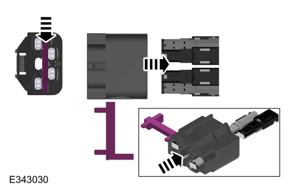
To test the Ethernet cable in question at the GWM , the cable must be removed from the GWM master connector to gain access to the connector pins where probing can take place (refer to the illustration above). The Ethernet cable connector end identification
color can be used to identify the module the Ethernet cable is connected
to. Refer to the chart in the Description and Operation section for the
color assignment. REFER to: Ethernet Module Communications Network -
System Operation and Component Description (418-00B Ethernet Module
Communications Network, Description and Operation). 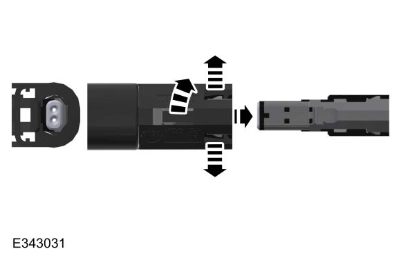
To test the Ethernet cable in question at the all other applicable modules, the cable must be removed from the connector housing to gain access to the connector pins where probing can take place. (refer to the illustration above) Ethernet Cable Testing At Cable In-line Connection 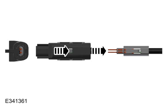
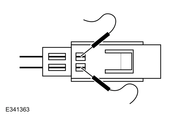
To test the Ethernet cable in question at the in-line connection, the cable must be removed from the connector housing to gain access to the connector pins where probing can take place (refer to the illustration above).
REFER to: Ethernet Module Communications Network - System Operation and
Component Description (418-00B Ethernet Module Communications Network,
Description and Operation). DTC Fault Trigger Conditions
Possible Sources
|
||||||||||||||||||||||||||||||||||||
| A1 CHECK THE NETWORK COMMUNICATION | ||||||||||||||||||||||||||||||||||||
Does the module in question (APIM , TCU , IPC , IPMA ) pass the network test?
|
||||||||||||||||||||||||||||||||||||
| A2 CHECK FOR DIAGNOSTIC TROUBLE CODES (DTCS) | ||||||||||||||||||||||||||||||||||||
Are any non-Ethernet related Diagnostic Trouble Codes (DTCs) present?
|
||||||||||||||||||||||||||||||||||||
| A3 CHECK THE ETHERNET CIRCUIT FOR A SHORT TO GROUND | ||||||||||||||||||||||||||||||||||||
Are the resistances greater than 10,000 ohms?
|
||||||||||||||||||||||||||||||||||||
| A4 CHECK THE ETHERNET CIRCUIT FOR A SHORT TOGETHER | ||||||||||||||||||||||||||||||||||||
Is the resistance greater than 10,000 ohms?
|
||||||||||||||||||||||||||||||||||||
| A5 CHECK THE ETHERNET CIRCUIT FOR A SHORT TO POWER | ||||||||||||||||||||||||||||||||||||
Is any voltage present?
|
||||||||||||||||||||||||||||||||||||
| A6 CHECK THE ETHERNET CIRCUIT FOR AN OPEN | ||||||||||||||||||||||||||||||||||||
Are the resistances less than 3 ohms?
|
||||||||||||||||||||||||||||||||||||
| A7 RECHECK FOR DIAGNOSTIC TROUBLE CODES (DTCS) | ||||||||||||||||||||||||||||||||||||
Is the DTC still present?
|
||||||||||||||||||||||||||||||||||||
| A8 CHECK FOR CORRECT APIM (SYNC MODULE) OPERATION | ||||||||||||||||||||||||||||||||||||
Is the concern still present?
|
||||||||||||||||||||||||||||||||||||
| A9 CHECK FOR CORRECT TCU (TELEMATIC CONTROL UNIT MODULE) OPERATION | ||||||||||||||||||||||||||||||||||||
Is the concern still present?
|
||||||||||||||||||||||||||||||||||||
| A10 CHECK FOR CORRECT IPC (INSTRUMENT PANEL CLUSTER) OPERATION | ||||||||||||||||||||||||||||||||||||
Is the concern still present?
|
||||||||||||||||||||||||||||||||||||
| A11 CHECK FOR CORRECT IPMA (IMAGE PROCESSING MODULE A) OPERATION | ||||||||||||||||||||||||||||||||||||
Is the concern still present?
|
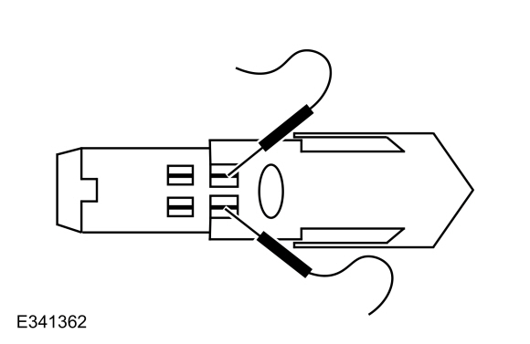
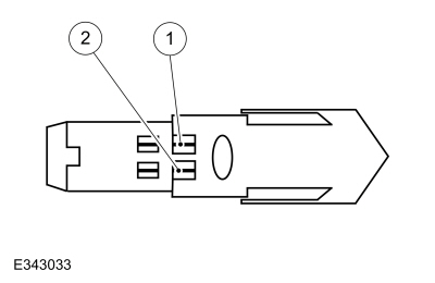 Ethernet cable , pin 1


|
Refer to Wiring Diagrams Cell 14 for schematic and connector information. Normal Operation and Fault Conditions Ethernet Cable Testing At Cable End
To test the Ethernet cable in question at the GWM , the cable must be removed from the GWM master connector to gain access to the connector pins where probing can take place (refer to the illustration above). The Ethernet cable connector end identification
color can be used to identify the module the Ethernet cable is connected
to. Refer to the chart in the Description and Operation section for the
color assignment. REFER to: Ethernet Module Communications Network -
System Operation and Component Description (418-00B Ethernet Module
Communications Network, Description and Operation).
To test the Ethernet cable in question at the all other applicable modules, the cable must be removed from the connector housing to gain access to the connector pins where probing can take place. (refer to the illustrations above) Ethernet Cable Testing At Cable In-line Connection
To test the Ethernet cable in question at the in-line connection, the cable must be removed from the connector housing to gain access to the connector pins where probing can take place (refer to the illustrations above).
REFER to: Ethernet Module Communications Network - System Operation and
Component Description (418-00B Ethernet Module Communications Network,
Description and Operation). DTC Fault Trigger Conditions
Possible Sources
|
|||||||||||||
| B1 CHECK THE NETWORK COMMUNICATION | |||||||||||||
Does the module in question (APIM , TCU ) pass the network test?
|
|||||||||||||
| B2 CHECK FOR DIAGNOSTIC TROUBLE CODES (DTCS) | |||||||||||||
Are any Diagnostic Trouble Codes (DTCs) present?
|
|||||||||||||
| B3 RESET THE MODULE IN QUESTION (APIM, TCU) | |||||||||||||
Does the authorization state PID still indicate Unprovisioned?
|
|||||||||||||
| B4 RECHECK FOR DIAGNOSTIC TROUBLE CODES (DTCS) | |||||||||||||
Is DTC U2401:00 or U2402:00 still present?
|
|||||||||||||
| B5 CHECK THE ETHERNET CIRCUIT FOR AN OPEN | |||||||||||||
Are the resistances less than 3 ohms?
|
|||||||||||||
| B6 CHECK THE ETHERNET CIRCUIT FOR A SHORT TO GROUND | |||||||||||||
Are the resistances greater than 10,000 ohms?
|
|||||||||||||
| B7 CHECK THE ETHERNET CIRCUIT FOR A SHORT TOGETHER | |||||||||||||
Is the resistance greater than 10,000 ohms?
|
|||||||||||||
| B8 CHECK THE ETHERNET CIRCUIT FOR A SHORT TO POWER | |||||||||||||
Is any voltage present?
|
|||||||||||||
| B9 CHECK FOR CORRECT APIM (SYNC MODULE) OPERATION | |||||||||||||
Is the concern still present?
|
|||||||||||||
| B10 CHECK FOR CORRECT TCU (TELEMATIC CONTROL UNIT MODULE) OPERATION | |||||||||||||
Is the concern still present?
|
|
Refer to Wiring Diagrams Cell 14 for schematic and connector information. Normal Operation and Fault Conditions All Ethernet connected modules are learned through the Ethernet
learning mode at key on. If all modules are not learned thisDTC is set.
If the Ethernet module is learned at a subsequent key on event, the DTC
is cleared. REFER to: Ethernet Module Communications Network - System
Operation and Component Description (418-00B Ethernet Module
Communications Network, Description and Operation). DTC Fault Trigger Conditions
Possible Sources
|
||||||
| C1 CHECK FOR DIAGNOSTIC TROUBLE CODES (DTCS) | ||||||
Is DTC U2120:00 the only DTC present?
|
||||||
| C2 RE-CHECK FOR DIAGNOSTIC TROUBLE CODES (DTCS) | ||||||
Is DTC U2120:00 still present?
|
||||||
| C3 CHECK THE NETWORK COMMUNICATION | ||||||
Do the APIM , IPC , IPMA and TCU pass the network test?
|
||||||
| C4 CHECK FOR DIAGNOSTIC TROUBLE CODES (DTCS) | ||||||
Are any Diagnostic Trouble Codes (DTCs) present?
|
||||||
| C5 CHECK FOR CORRECT GWM (GATEWAY MODULE A) OPERATION | ||||||
Is the concern still present?
|
 Ethernet Module Communications Network - System Operation and Component Description. Description and Operation
System Operation
System Diagram
NOTE:
The system diagrams include all component options. Some components may not be equipped on the vehicle.
Ethernet Communication Network
*...

Other information:
Lincoln Navigator 2018-2026 Workshop Manual: Thermostat Housing. Removal and Installation
Special Tool(s) / General Equipment Hose Clamp Remover/Installer Materials Name Specification Motorcraft® Yellow Concentrated Antifreeze/CoolantVC-13-G WSS-M97B57-A1 Motorcraft® Orange Concentrated Antifreeze/CoolantVC-3-B WSS-M97B44-D Removal NOTE: Removal steps in this procedure may contain installation details. ..
Lincoln Navigator 2018-2026 Workshop Manual: Blower Motor Control Module. Removal and Installation
Removal NOTE: Removal steps in this procedure may contain installation details. Remove the push pins and the RH insulation panel. If equipped, disconnect the electrical connector. NOTE: Vehicles equipped with TCCM . Remove the BCM cover. NOTE: Vehicles eq..
Categories
- Manuals Home
- 4th Gen Lincoln Navigator Service Manual (2018 - 2026)
- Remote Function Actuator (RFA) Module. Removal and Installation
- Body and Paint
- Head Up Display (HUD) Module Calibration. General Procedures
- All Terrain Control Module (ATCM). Removal and Installation
- Power Running Board (PRB). Diagnosis and Testing
Front Driveshaft. Removal and Installation
Special Tool(s) / General Equipment
Crimping ToolMaterials
Name Specification Motorcraft® Premium Long-Life GreaseXG-1-E1 ESA-M1C75-B
Removal
With the vehicle in NEUTRAL, position the vehicle on a hoist.Refer to: Jacking and Lifting (100-02 Jacking and Lifting, Description and Operation).
Remove the bolts and the transmission shield.