Lincoln Navigator: Engine - 3.5L EcoBoost (272kW/370PS) / Engine - Overview. Description and Operation
Overview
The 3.5L Ecoboost is a turbocharged engine which may also be described with these terms:
- GTDI - Gasoline Turbocharged Direct Injection
- DI - Direct Injection
- GT - Gasoline Turbocharged
- Ti-VCT TC - Twin independent Variable Camshaft Timing Turbocharged
- V6 - 6 cylinder engine
- 24V - 4 valves per cylinder
- 4V - 4 valves per cylinder, 24 valves total
3.5L EcoBoost (440PS)
- 3.5L - Engine displacement
- Ecoboost - Turbocharged engine
- 440PS - Engine power rating
The 3.5L EcoBoost (4V) is a V-6 engine with the following features:
- Dual overhead camshafts
- Four valves per cylinder
- Gasoline Turbocharged Direct Injection (GTDI) with Port Fuel Injection (PFI)
- Composite intake manifold
- Aluminum cylinder heads
- An aluminum, 60-degree V-cylinder block
- Twin independent Variable Camshaft Timing (Ti-VCT)
- An electronic ignition system with 6 ignition coils
Engine Identification
For quick identification, refer to the safety certification decal.
The decal is located on the LH front door lock face panel.
Engine Code Information Label
The engine code information label, located on the front side of the valve cover, contains the following:
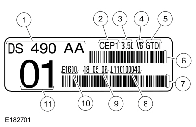
| Item | Description |
|---|---|
| 1 | Engine part number |
| 2 | Engine plant (Cleveland) |
| 3 | Engine displacement |
| 4 | Engine configuration |
| 5 | Gasoline Turbocharged Direct Injection (GTDI) |
| 6 | Bar code |
| 7 | Bar code |
| 8 | Running number |
| 9 | Engine build date (DDMMYY) |
| 10 | Plant shift line |
| 11 | Derivative code |
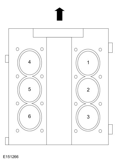
Engine Cylinder Identification
System Operation
Lubrication System
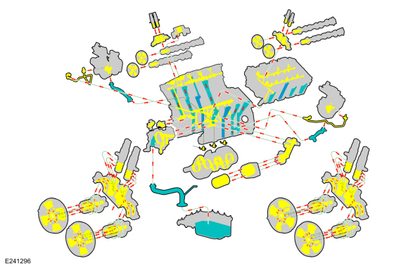
| Item | Description |
|---|---|
| Yellow | High pressure oil flow |
| Blue | Oil return/low pressure oil flow |
Oil Pump
The engine lubrication system is of the force-feed type in which oil is supplied under full pressure to the crankshaft, connecting rod bearings, timing chain tensioners, piston oil cooling jets, turbochargers and VCT solenoids. The flow of oil to the valve tappets and valve train is controlled by a restricting orifices located in the each of the cylinder head oil galleries.
The lubrication system is designed to provide optimum oil flow to critical components of the engine through its entire operating range.
The heart of the system is a positive displacement internal 2-stage variable vane oil pump.
- The oil pump is mounted on the front face of the cylinder block.
- The rotor is piloted on the crankshaft post and is driven through flats on the crankshaft.
- Maximum system pressure is limited by an integral, internally-vented relief valve which directs the excess oil back to the oil pan.
- Oil pump displacement has been selected to provide adequate volume to make sure of correct oil pressure both at hot idle and maximum speed.
- The relief valve calibration protects the system from excessive pressure during high-viscosity conditions.
- The relief valve is designed to provide adequate connecting rod bearing lubrication under high temperature and high-speed conditions.
- 2-stage operation of the oil pump is controlled by an integral solenoid on the pump that will switch the pump between high and low mode operation.
- The engine PCM sends a 12v signal to the oil pump solenoid to switch the pump to low mode. Default is no voltage or high mode operation.
- Both low and high mode maintain required oil pressure to protect and maintain engine function at their specified speeds, engine load (throttle position), and engine temperature.
- Low mode operation is designed to maintain oil pressure between 20 to 30 psi at speeds from 1000 to 3000 rpm with low engine load and engine oil temperatures at normal operating conditions.
- High mode operation is at all other engine operating conditions.
Twin Independent Variable Camshaft Timing (Ti-VCT)
The Twin independent VCT system allows variable control of the valves which optimizes combustion at full load providing improved power and low speed torque (broadening the torque curve) which enables variable valve overlap which provides better fuel economy and emissions and provides optimized cold start operation with improved exhaust emissions.

 Engine. Diagnosis and Testing
For gas engine mechanical diagnosis and testing, REFER to: Engine (303-00 Engine System - General Information, Diagnosis and Testing). For DTC (Diagnostic Trouble Code) related concerns, REFER to the Master DTC Chart...
Other information:
Lincoln Navigator 2018-2026 Workshop Manual: Steering Column Multifunction Switch LH. Removal and Installation
Removal NOTE: Removal steps in this procedure may contain installation details. Remove the steering column shrouds. Refer to: Steering Column Shrouds (501-05 Interior Trim and Ornamentation, Removal and Installation). If equipped...
Lincoln Navigator 2018-2026 Workshop Manual: Roof Side Rail Section. Removal and Installation
Special Tool(s) / General Equipment 6.5 mm Drill Bit Polydrive Bit Socket Self-Piercing Rivet (SPR) Remover/Installer Belt Sander Blind Rivet Gun Air Body Saw MIG/MAG Welding Equipment Locking Pliers Materials Name Specification Metal Bonding AdhesiveTA-1, TA-1-B, 3M™ 08115, LORD Fusor® 108B, Henkel Teroson ..
Categories
- Manuals Home
- 4th Gen Lincoln Navigator Service Manual (2018 - 2026)
- SYNC Module [APIM]. Removal and Installation
- Transmission Fluid Level Check. General Procedures
- Liftgate Trim Panel. Removal and Installation
- Neutral Flat Tow Activation and Deactivation. General Procedures
- Windshield Washer Pump. Removal and Installation
Rear Drive Axle and Differential. Diagnosis and Testing
Symptom Chart(s)
Diagnostics in this manual assume a certain skill level and knowledge of Ford-specific diagnostic practices.
REFER to: Diagnostic Methods (100-00 General Information, Description and Operation).
Symptom Chart - Differential
Symptom Chart - Differential
Condition Actions Axle overheating GO to Pinpoint Test A Broken gear teeth on the ring gear or pinion GO to Pi