Lincoln Navigator: Engine Ignition - 3.5L EcoBoost (272kW/370PS) / Engine Ignition - Component Location. Description and Operation
3.5L EcoBoost
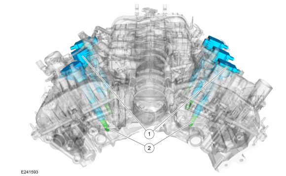
| Item | Description |
|---|---|
| 1 | Ignition coil-on-plug(s) |
| 2 | Spark plug(s) |
 Specifications
General Specifications
Item
Specification
Spark plug
12405
Spark plug gap
0...
 Engine Ignition - System Operation and Component Description. Description and Operation
System Operation
Cold Start Emission Reduction Monitor
The
cold start emission reduction monitor is an on board strategy designed
for vehicles that meet the low emissions vehicle-II (LEV-II) emissions
standards...
Other information:
Lincoln Navigator 2018-2026 Workshop Manual: Liftgate Window Glass. Removal and Installation
Removal NOTE: Removal steps in this procedure may contain installation details. Open the liftgate window glass. NOTE: Liftgate shown closed for clarity. Disconnect the heated rear window element electrical connectors...
Lincoln Navigator 2018-2026 Workshop Manual: Air Conditioning (A/C) Odor Treatment. General Procedures
Inspection NOTE: There are typically 4 types of objectionable odors found in a vehicle: chemical odors environmental odors human and other interior-generated odors microbiological odors Before determining that A/C odor treatment is required, determine the source and the circumstances under which the odor occurs...
Categories
- Manuals Home
- 4th Gen Lincoln Navigator Service Manual (2018 - 2026)
- Brake Service Mode Activation and Deactivation. General Procedures
- Vehicle Dynamics Control Module (VDM). Removal and Installation
- Transmission Fluid Level Check. General Procedures
- Transmission Fluid Drain and Refill. General Procedures
- All Terrain Control Module (ATCM). Removal and Installation
Wheel to Hub Runout Minimization. General Procedures
Check
NOTE: Wheel-to-hub optimization is important. Clearance between the wheel and hub can be used to offset or neutralize the Road Force® or run-out of the wheel and tire assembly. For every 0.001 inch of wheel-to-hub clearance, the Road Force® can be affected between 1 and 3 pounds depending on the tire stiffness.
NOTE: The example below illustrates how the clearance between the wheel and the hub can be used to offset the high spot of radial run-out or Road Force®. Following the procedure will make sure of the best optimization.
Position the wheel and tire assembly on the vehicle so that the high spot location of radial run-out or Road Force® is at the 6 o'clock position and