Lincoln Navigator: Parking Aid / Elevation System Check. General Procedures
Check
-
Turn the ignition ON, engine OFF.
 |
-
Set the parking brake.
-
Place the gearshift in REVERSE (R) for rear parking aid sensors.
-
Place the gearshift in DRIVE (D) for front parking aid sensors.
-
Using a diagnostic scan tool, monitor the parking aid
sensor distance Parameter Identifications (PIDs) to verify no objects
are detected.
-
If the audible warning is heard or if the Parameter
Identifications (PIDs) indicate an object is detected, check to make
sure the bumper is correctly installed and is not tilted downward so the
sensor is pointing at the ground. Refer to Diagnosis and Testing.
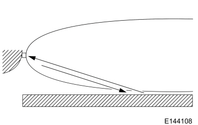
 Azimuth System Check. General Procedures
Check
NOTE:
The object used in this system check can be
fabricated using a 9 cm diameter (3 in I.D.) pipe, 100 cm (39 in) in
length (available as Polyvinyl Chloride (PVC) pipe, or similar from a
hardware or plumbing supply...
 Front Parking Aid Sensor. Removal and Installation
Removal
NOTE:
Removal steps in this procedure may contain installation details.
NOTE:
RH side shown, LH side similar.
With the vehicle in NEUTRAL, position it on a hoist...
Other information:
Lincoln Navigator 2018-2026 Workshop Manual: Charge Air Cooler (CAC). Removal and Installation
Removal NOTICE: The turbocharger compressor vanes can be damaged by even the smallest particles. When removing any turbocharger or engine air intake system component, ensure that no debris enters the system. Failure to do so may result in damage to the turbocharger...
Lincoln Navigator 2018-2026 Workshop Manual: Body System. Diagnosis and Testing
Symptom Chart(s) Diagnostics in this manual assume a certain skill level and knowledge of Ford-specific diagnostic practices. REFER to: Diagnostic Trouble Code Charts (100-00) . Dust and Water Leaks Most dust and water leaks occur due to missing or incorrectly installed body sealer or components...
Categories
- Manuals Home
- 4th Gen Lincoln Navigator Service Manual (2018 - 2026)
- Rear View Mirrors - System Operation and Component Description. Description and Operation
- Front Seat. Removal and Installation
- SYNC Module [APIM]. Removal and Installation
- Transmission Fluid Level Check. General Procedures
- Identification Codes. Description and Operation
Wheel to Hub Runout Minimization. General Procedures
Check
NOTE: Wheel-to-hub optimization is important. Clearance between the wheel and hub can be used to offset or neutralize the Road Force® or run-out of the wheel and tire assembly. For every 0.001 inch of wheel-to-hub clearance, the Road Force® can be affected between 1 and 3 pounds depending on the tire stiffness.
NOTE: The example below illustrates how the clearance between the wheel and the hub can be used to offset the high spot of radial run-out or Road Force®. Following the procedure will make sure of the best optimization.
Position the wheel and tire assembly on the vehicle so that the high spot location of radial run-out or Road Force® is at the 6 o'clock position and