Lincoln Navigator: Anti-Lock Brake System (ABS) and Stability Control / Electric Brake Booster (EBB). Removal and Installation
Removal
NOTE: Removal steps in this procedure may contain installation details.
NOTE: The EBB and the ABS module are serviced as an assembly and should not be separated.
-
NOTE: The PMI process must begin with the current ABS module installed. If the current ABS module does not respond to the diagnostic scan tool, the tool may prompt for As-Built Data as part of the repair.
Using a diagnostic scan tool, begin the PMI process for the ABS module following the onscreen instructions.
-
Disconnect the ABS module and brake fluid level sensor electrical connectors.
 |
-
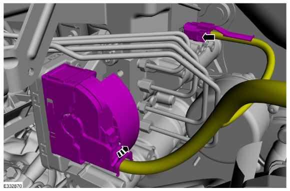
NOTICE: If the brake fluid is spilled on any component, the affected area must be immediately washed down with cold water.
NOTE: Make sure that all openings are sealed.
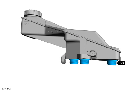
Disconnect the brake tube fittings.
Torque: 159 lb.in (18 Nm)
 |
-
-
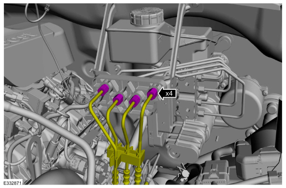
Disconnect the brake tube fittings.
Torque: 159 lb.in (18 Nm)
-
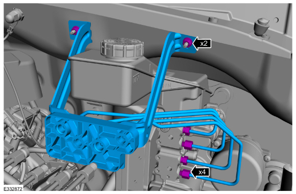
Remove the nuts and the brake tube assembly.
Torque: 97 lb.in (11 Nm)
-
Disconnect the brake tube fittings.
 |
-
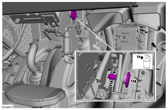
Push inward on the tabs and remove the clevis pin. Discard the pin.
 |
-
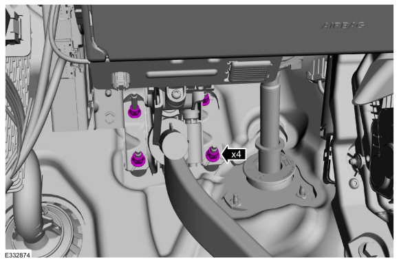
Remove the EBB nuts.
Torque: 17 lb.ft (23 Nm)
 |
-
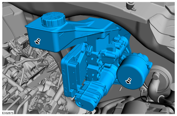
Remove the EBB .
 |
-
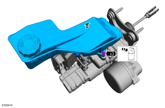
Remove the screws and the brake fluid reservoir. Discard the screws.
 |
-
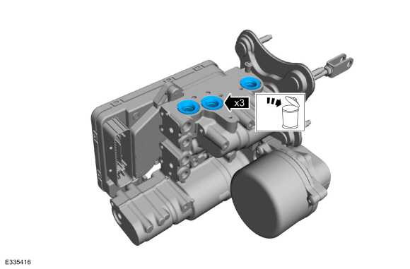
Remove and discard the brake fluid reservoir seals.
 |
Installation
-
Install the new brake fluid reservoir seals on the brake fluid reservoir before installing the reservoir.
 |
-
To install, reverse the removal procedure.
-
Using a diagnostic scan tool, complete the PMI process for the ABS module following the on-screen instructions.
-
Carry out the following service functions using the scan
tool and following the diagnostic scan tool on-screen instructions.
-
Carry out the ABS Brake System Pressure Bleeding and Bleed Check.
-
Carry out the ABS Calibration.
-
Carry out the IVD Initialization.
-
Carry out the EPB initialization.
-
Run the PCM
PATS
programming application and then carry out the Module Initialization
(Parameter Reset) using the scan tool and following the diagnostic scan
tool on-screen instructions.
-
Carry out the ABS Brake System Pressure Bleeding and Bleed Check.
 Anti-Lock Brake System (ABS) and Stability Control. Diagnosis and Testing
Diagnostic Trouble Code (DTC) Chart
Diagnostics in this manual assume a certain skill level and knowledge of Ford-specific diagnostic practices. REFER to: Diagnostic Methods (100-00 General Information, Description and Operation)...
 Front Wheel Speed Sensor. Removal and Installation
Materials
Name
Specification
Motorcraft® Metal Brake Parts CleanerPM-4-A, PM-4-B, APM-4-C
-
Removal
NOTE:
Removal steps in this procedure may contain installation details...
Other information:
Lincoln Navigator 2018-2026 Workshop Manual: Instrument Panel Center Finish Panel. Removal and Installation
Special Tool(s) / General Equipment Interior Trim Remover Removal NOTE: Removal steps in this procedure may contain installation details. Release the clips and emove the center finish panel. Disconnect the electrical connector...
Lincoln Navigator 2018-2026 Workshop Manual: Telematics Control Unit (TCU) Module. Removal and Installation
Removal NOTE: Removal steps in this procedure may contain installation details. NOTE: If installing a new module, it is necessary to upload the module configuration information to the scan tool prior to removing the module. This information must be downloaded into the new module after installation...
Categories
- Manuals Home
- 4th Gen Lincoln Navigator Service Manual (2018 - 2026)
- Transmission Fluid Level Check. General Procedures
- Brake Service Mode Activation and Deactivation. General Procedures
- All Terrain Control Module (ATCM). Removal and Installation
- SYNC Module [APIM]. Removal and Installation
- Body and Paint
Rear Stabilizer Bar Link. Removal and Installation
Removal
NOTE: Removal steps in this procedure may contain installation details.
With the vehicle in NEUTRAL, position it on a hoist.Refer to: Jacking and Lifting (100-02 Jacking and Lifting, Description and Operation).
NOTE: Use the hex-holding feature to prevent the stud from turning while removing the nut.
Remove and discard the 2 rear stabilizer bar link nuts and remove the rear stabilizer bar link.Torque: 46 lb.ft (63 Nm)
