Lincoln Navigator: Cruise Control - Vehicles With: Adaptive Cruise Control / Cruise Control. Diagnosis and Testing
Diagnostic Trouble Code (DTC) Chart
Diagnostics in this manual assume a certain skill level and knowledge of Ford-specific diagnostic practices.
REFER to: Diagnostic Methods (100-00 General Information, Description and Operation).
| Module | DTC | Description | Action |
|---|---|---|---|
| CCM | B142E:78 | Forward Looking Sensor Horizontal Alignment: Alignment Or Adjustment Incorrect | GO to Pinpoint Test D |
| CCM | B1432:78 | Forward Looking Sensor Vertical Alignment: Alignment Or Adjustment Incorrect | GO to Pinpoint Test D |
| CCM | B1433:54 | Forward Looking Sensor Alignment: Missing Calibration | GO to Pinpoint Test D |
| CCM | C1A67:96 | Forward Looking Sensor: Component Internal Failure | GO to Pinpoint Test E |
| CCM | C1A67:97 | Forward Looking Sensor: Component Or System Operation Obstructed Or Blocked | GO to Pinpoint Test F |
| CCM | C1A67:98 | Forward Looking Sensor: Component Or System Over Temperature | GO to Pinpoint Test G |
| CCM | U2008:08 | Sensor Cluster: Bus Signal/Message Failures | GO to Pinpoint Test H |
| CCM | U2100:00 | Initial Configuration Not Complete: No Sub Type Information | GO to Pinpoint Test I |
| CCM | U2300:55 | Central Configuration: Not Configured | GO to Pinpoint Test I |
| CCM | U3000:41 | Control Module: General Checksum Failure | GO to Pinpoint Test J |
| CCM | U3000:42 | Control Module: General Memory Failure | GO to Pinpoint Test J |
| CCM | U3000:44 | Control Module: Data Memory Failure | GO to Pinpoint Test J |
| CCM | U3000:49 | Control Module: Internal Electronic Failure | GO to Pinpoint Test J |
| CCM | U3002:62 | Vehicle Identification Number: Signal Compare Failure | GO to Pinpoint Test K |
| CCM | U3003:16 | Battery Voltage: Circuit Voltage Below Threshold | GO to Pinpoint Test L |
| CCM | U3003:17 | Battery Voltage: Circuit Voltage Above Threshold | GO to Pinpoint Test M |
| PCM | P0504:00 | Brake Switch 'A'/'B' Correlation: No Sub Type Information | GO to Pinpoint Test C |
| PCM | P0572:00 | Brake Switch 'A' Circuit Low: No Sub Type Information | GO to Pinpoint Test C |
| PCM | P0573:00 | Brake Switch 'A' Circuit High: No Sub Type Information | GO to Pinpoint Test C |
| PCM | P1703:00 | Brake Switch Out Of Self Test Range: No Sub Type Information | GO to Pinpoint Test C |
| PCM | P1935:00 | Brake Switch/Sensor Signal: No Sub Type Information | GO to Pinpoint Test C |
| SCCM | B137F:11 | Steering Wheel Left Switch Pack: Circuit Short To Ground | GO to Pinpoint Test B |
| SCCM | B137F:13 | Steering Wheel Left Switch Pack: Circuit Open | GO to Pinpoint Test B |
| SCCM | B137F:96 | Steering Wheel Left Switch Pack: Component Internal Failure | GO to Pinpoint Test B |
| SCCM | B137F:9E | Steering Wheel Left Switch Pack: Stuck On | GO to Pinpoint Test B |
| SCCM | B1380:11 | Steering Wheel Right Switch Pack: Circuit Short To Ground | GO to Pinpoint Test B |
| SCCM | B1380:13 | Steering Wheel Right Switch Pack: Circuit Open | GO to Pinpoint Test B |
| SCCM | B1380:96 | Steering Wheel Right Switch Pack: Component Internal Failure | GO to Pinpoint Test B |
| SCCM | B1380:9E | Steering Wheel Right Switch Pack: Stuck On | GO to Pinpoint Test B |
Global Customer Symptom Code (GCSC) Chart
Diagnostics in this manual assume a certain skill level and knowledge of Ford-specific diagnostic practices.
REFER to: Diagnostic Methods (100-00 General Information, Description and Operation).
| Symptom | Action |
|---|---|
| Driver Aid & Information > Steering Wheel Controls > Performance > Inoperative | GO to Pinpoint Test B |
| Driver Aid & Information > Warning Indicators/Messages/Chimes > Collision Avoidance > Inoperative | GO to Pinpoint Test A |
| Driver Aid & Information > Forward Sensing > Performance > Inoperative | GO to Pinpoint Test N |
Symptom Chart(s)
Symptom Chart: ACC
Diagnostics in this manual assume a certain skill level and knowledge of Ford-specific diagnostic practices.
REFER to: Diagnostic Methods (100-00 General Information, Description and Operation).
Symptom Chart
| Condition | Possible Sources | Actions |
|---|---|---|
| The CCM does not communicate with the diagnostic scan tool | Refer to the Pinpoint Test | GO to Pinpoint Test A |
| The ACC is inoperative | Refer to the Pinpoint Test | GO to Pinpoint Test B |
| The cruise control switch is inoperative/does not operate correctly | Refer to the Pinpoint Test | GO to Pinpoint Test B |
| The ACC does not function in rain or snow conditions | Refer to the Pinpoint Test | GO to Pinpoint Test F |
| ADAPTIVE CRUISE NOT AVAILABLE SENSOR BLOCKED SEE MANUAL message in the IPC message center | Refer to the Pinpoint Test | GO to Pinpoint Test F |
| Unexpected ACC braking | Refer to the Pinpoint Test | GO to Pinpoint Test N |
| Lack of ACC braking | Refer to the Pinpoint Test | GO to Pinpoint Test N |
| ACC does not slow the vehicle down until too close to a lead vehicle, does not detect a lead vehicle or vehicle follows closer than the set gap value | Refer to the Pinpoint Test | GO to Pinpoint Test N |
| Collision warning alerts in high sensitivity setting occur on bridges | Refer to the Pinpoint Test | GO to Pinpoint Test N |
Pinpoint Tests
|
Refer to Wiring Diagrams Cell 31 for schematic and connector information. Normal Operation and Fault Conditions The CCM communicates with the diagnostic scan tool through the IPMA
on a private CAN circuit. REFER to: Cruise Control - System Operation
and Component Description (419-03A Cruise Control - Vehicles With:
Adaptive Cruise Control, Description and Operation). Possible Sources
|
||||
| A1 CHECK FOR IPMA (IMAGE PROCESSING MODULE A) DIAGNOSTIC TROUBLE CODES (DTCS) | ||||
Are any network or non-network DTCs recorded?
|
|
Refer to Wiring Diagrams Cell 31 for schematic and connector information. Normal Operation and Fault Conditions If the cruise control does not set above 105 kmh (65 mph), 113 kmh (70 mph), 121 kmh (75 mph) or 129 kmh (80 mph), a MyKey® restricted key is in use and MyKey® maximum speed limiter is turned on. With an administration key, verify if the MyKey® maximum speed limiter is turned on. For additional information, refer to the Owner's Literature.
REFER to: Cruise Control - System Operation and Component Description
(419-03A Cruise Control - Vehicles With: Adaptive Cruise Control,
Description and Operation). DTC Fault Trigger Conditions
Possible Sources
NOTE: Some Antilock Brake System (ABS) module Diagnostic Trouble Codes (DTCs) may inhibit Adaptive Cruise Control (ACC) operation. Check for ABS module DTCs, REFER to section 206-09. |
|||||||||||||||||||||||||||||||
| B1 CHECK FOR DIAGNOSTIC TROUBLE CODES (DTCS) | |||||||||||||||||||||||||||||||
Are any DTCs recorded?
|
|||||||||||||||||||||||||||||||
| B2 CHECK FOR LOST COMMUNICATION DTCS | |||||||||||||||||||||||||||||||
Are any lost communication DTCs set in the CCM ?
|
|||||||||||||||||||||||||||||||
| B3 CHECK THE STOPLAMP SWITCH (BOO1) AND CRUISE CONTROL DEACTIVATOR SWITCH (BOO2) PARAMETER IDENTIFICATIONS (PIDS) | |||||||||||||||||||||||||||||||
Do the PID values agree with the brake pedal position?
|
|||||||||||||||||||||||||||||||
| B4 CHECK FOR VOLTAGE AT THE STEERING WHEEL SWITCH | |||||||||||||||||||||||||||||||
Is the voltage approximately 5 volts?
|
|||||||||||||||||||||||||||||||
| B5 CHECK THE STEERING WHEEL HARNESS | |||||||||||||||||||||||||||||||
Are the voltages approximately 5 volts?
|
|||||||||||||||||||||||||||||||
| B6 CHECK THE CLOCKSPRING FOR AN OPEN | |||||||||||||||||||||||||||||||
Are the resistances 1 ohm or less?
|
|||||||||||||||||||||||||||||||
| B7 CHECK FOR CORRECT SCCM (STEERING COLUMN CONTROL MODULE) OPERATION | |||||||||||||||||||||||||||||||
Is the concern still present?
|
|||||||||||||||||||||||||||||||
| B8 CHECK FOR CORRECT PCM (POWERTRAIN CONTROL MODULE) OPERATION | |||||||||||||||||||||||||||||||
Is the concern still present?
|

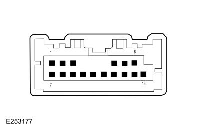 Upper Clockspring C218B, pin 7 (component side)

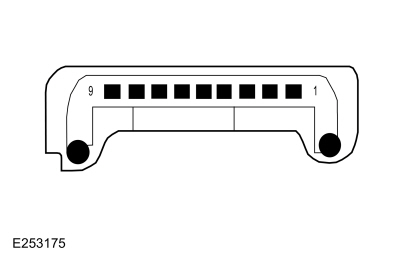 Lower Clockspring pin 1 (component side)
 Click here to access Guided Routine (PCM).
|
Refer to Wiring Diagrams Cell 31 for schematic and connector information. Normal Operation and Fault Conditions
REFER to: Cruise Control - System Operation and Component Description
(419-03A Cruise Control - Vehicles With: Adaptive Cruise Control,
Description and Operation). DTC Fault Trigger Conditions
Possible Sources
NOTICE: Use the correct probe adapter(s) when making measurements. Failure to use the correct probe adapter(s) may damage the connector. |
||||||||||||||||||
| C1 CHECK FOR DIAGNOSTIC TROUBLE CODES (DTCS) | ||||||||||||||||||
Are any DTCs recorded?
|
||||||||||||||||||
| C2 CHECK THE OPERATION OF THE STOPLAMPS | ||||||||||||||||||
Do the stoplamps and high mounted stoplamp operate correctly?
|
||||||||||||||||||
| C3 CHECK THE STOPLAMP SWITCH (BOO1) AND CRUISE CONTROL DEACTIVATOR SWITCH (BOO2) PARAMETER IDENTIFICATIONS (PIDS) | ||||||||||||||||||
Do the PID values agree with the brake pedal position?
|
||||||||||||||||||
| C4 CHECK THE BRAKE POSITION SWITCH INPUT CIRCUIT FOR A SHORT TO VOLTAGE | ||||||||||||||||||
Is any voltage present?
|
||||||||||||||||||
| C5 CHECK THE BRAKE POSITION SWITCH INPUT CIRCUIT FOR A SHORT TO GROUND | ||||||||||||||||||
Is the resistance greater than 10,000 ohms?
|
||||||||||||||||||
| C6 CHECK THE BRAKE POSITION SWITCH INPUT CIRCUIT FOR AN OPEN | ||||||||||||||||||
Is the resistance less than 1 ohm?
|
||||||||||||||||||
| C7 CHECK FOR CORRECT PCM (POWERTRAIN CONTROL MODULE) OPERATION | ||||||||||||||||||
Is the concern still present?
|
|
Refer to Wiring Diagrams Cell 31 for schematic and connector information. Normal Operation and Fault Conditions
REFER to: Cruise Control - System Operation and Component Description
(419-03A Cruise Control - Vehicles With: Adaptive Cruise Control,
Description and Operation). DTC Fault Trigger Conditions
Possible Sources
NOTE: The CCM radar vertical and horizontal alignment procedure is located in General Procedures. The horizontal alignment for the CCM is a calibration check performed by the scan tool to insure the CCM radar is pointed straight. The scan tool identifies this as, Alignment Offset ( Access the CCM and monitor the ALGN_OFF (Deg) PID ) with a horizontal specification of +/- 3.0 degrees offset.NOTE: Inspect for vision system alingment or calbration Diagnostic Trouble Codes (DTCs) are present. |
||||||||||||
| D1 CHECK FOR DIAGNOSTIC TROUBLE CODES (DTCS) | ||||||||||||
Are any DTCs recorded?
|
||||||||||||
| D2 INSPECT THE CCM (CRUISE CONTROL MODULE) BRACKET | ||||||||||||
Is the CCM bracket damaged?
|
||||||||||||
| D3 PERFORM THE VERTICAL AND HORIZONTAL ALIGNMENT | ||||||||||||
Does the CCM align correctly?
|
||||||||||||
| D4 RECHECK FOR CCM (CRUISE CONTROL MODULE) DTCS | ||||||||||||
Is CCM DTC B142E:78, B1432:78 or B1433:54 recorded?
|
||||||||||||
| D5 CHECK FOR CORRECT CCM (CRUISE CONTROL MODULE) OPERATION | ||||||||||||
Is the concern still present?
|
|
Refer to Wiring Diagrams Cell 31 for schematic and connector information. Normal Operation and Fault Conditions
REFER to: Cruise Control - System Operation and Component Description
(419-03A Cruise Control - Vehicles With: Adaptive Cruise Control,
Description and Operation). DTC Fault Trigger Conditions
Possible Sources
|
||||||
| E1 CHECK THE CCM (CRUISE CONTROL MODULE) DIAGNOSTIC TROUBLE CODES (DTCS) | ||||||
Is DTC C1A67:96 recorded?
|
||||||
| E2 CHECK FOR CORRECT CCM (CRUISE CONTROL MODULE) OPERATION | ||||||
Is the concern still present?
|
|
Refer to Wiring Diagrams Cell 31 for schematic and connector information. Normal Operation and Fault Conditions
REFER to: Cruise Control - System Operation and Component Description
(419-03A Cruise Control - Vehicles With: Adaptive Cruise Control,
Description and Operation). DTC Fault Trigger Conditions
Possible Sources
|
||||||
| F1 INSPECT THE FRONT BUMPER COVER FOR DAMAGE | ||||||
Is the front bumper cover damaged?
|
||||||
| F2 INSPECT THE CCM (CRUISE CONTROL MODULE) AND FRONT BUMPER COVER | ||||||
Is the CCM obstructed or blocked?
|
||||||
| F3 INSPECT THE CCM (CRUISE CONTROL MODULE) BRACKET FOR CORRECT MOUNTING | ||||||
Is the CCM bracket loose, bent or damaged?
|
||||||
| F4 INSPECT THE CCM (CRUISE CONTROL MODULE) FOR EXTREME VERTICAL MISALIGNMENT | ||||||
Is the CCM visually misaligned vertically?
|
||||||
| F5 PERFORM HORIZONTAL AIM | ||||||
Does horizontal aim procedure finish successfully without setting DTC C1A67:97?
|
||||||
| F6 CHECK FOR CORRECT CCM (CRUISE CONTROL MODULE) OPERATION | ||||||
Is the concern still present?
|
|
Refer to Wiring Diagrams Cell 31 for schematic and connector information. Normal Operation and Fault Conditions
REFER to: Cruise Control - System Operation and Component Description
(419-03A Cruise Control - Vehicles With: Adaptive Cruise Control,
Description and Operation). DTC Fault Trigger Conditions
Possible Sources
NOTE: This DTC may occur during extremely high ambient temperature. Allow the CCM to cool. The ACC system operation resumes after the CCM cools. |
||||||
| G1 CHECK THE CCM (CRUISE CONTROL MODULE) DIAGNOSTIC TROUBLE CODES (DTCS) | ||||||
Is DTC C1A67:98 recorded?
|
||||||
| G2 CHECK FOR CORRECT CCM (CRUISE CONTROL MODULE) OPERATION | ||||||
Is the concern still present?
|
|
Refer to Wiring Diagrams Cell 31 for schematic and connector information. Normal Operation and Fault Conditions
REFER to: Cruise Control - System Operation and Component Description
(419-03A Cruise Control - Vehicles With: Adaptive Cruise Control,
Description and Operation). DTC Fault Trigger Conditions
Possible Sources
Visual Inspection and Pre-checks
NOTICE: Use the correct probe adapter(s) when making measurements. Failure to use the correct probe adapter(s) may damage the connector. |
|||||||||||||
| H1 PERFORM THE NETWORK TEST | |||||||||||||
Does the IPMA pass the network test?
|
|||||||||||||
| H2 CHECK THE PRIVATE CAN (CONTROLLER AREA NETWORK) CIRCUITS FOR A SHORT TO VOLTAGE | |||||||||||||
Is any voltage present?
|
|||||||||||||
| H3 CHECK THE PRIVATE CAN (CONTROLLER AREA NETWORK) CIRCUITS FOR A SHORT TO GROUND | |||||||||||||
Are the resistances greater than 10,000 ohms?
|
|||||||||||||
| H4 CHECK THE PRIVATE CAN (CONTROLLER AREA NETWORK) CIRCUITS FOR A SHORT TOGETHER | |||||||||||||
Is the resistance greater than 10,000 ohms?
|
|||||||||||||
| H5 CHECK THE PRIVATE CAN (CONTROLLER AREA NETWORK) CIRCUITS FOR AN OPEN | |||||||||||||
Are the resistances less than 1 ohm?
|
|||||||||||||
| H6 CHECK FOR CORRECT CCM (CRUISE CONTROL MODULE) OPERATION | |||||||||||||
Is the concern still present?
|
|||||||||||||
| H7 CHECK FOR CORRECT IPMA (IMAGE PROCESSING MODULE A) OPERATION | |||||||||||||
Is the concern still present?
|
|
Normal Operation and Fault Conditions The CCM as well as all control modules that are programmable must have the correct As-Built data installed. DTC Fault Trigger Conditions
Possible Sources
|
|||||||||
| I1 CONFIRM THE DTC (DIAGNOSTIC TROUBLE CODE) RESETS | |||||||||
Is DTC U2100:00 or U2300:55 still present?
|
|||||||||
| I2 INSTALL CCM (CRUISE CONTROL MODULE) PMI (PROGRAMMABLE MODULE INSTALLATION) | |||||||||
Is DTC U2100:00 or U2300:55 still present?
|
|
Refer to Wiring Diagrams Cell 31 for schematic and connector information. Normal Operation and Fault Conditions When the CCM receives an ignition wake up signal, the CCM preforms a state of health check. If checksum values, internal memory, internal electronic failure or a RAM failure occurs, then one or more of the following codes may set. DTC Fault Trigger Conditions
Possible Sources
|
|||||||||||||||
| J1 CHECK THE CCM (CRUISE CONTROL MODULE) DIAGNOSTIC TROUBLE CODES (DTCS) | |||||||||||||||
Is DTC U3000:41, U3000:42, U3000:44 or U3000:49 recorded?
|
|||||||||||||||
| J2 CHECK FOR CORRECT CCM (CRUISE CONTROL MODULE) OPERATION | |||||||||||||||
Is the concern still present?
|
|
Refer to Wiring Diagrams Cell 31 for schematic and connector information. Normal Operation and Fault Conditions When the CCM receives an ignition wale up signal, the CCM preforms a state of health check and verifies the VIN programmed in it's memory matches what's programmed into the BCM memory. DTC Fault Trigger Conditions
Possible Sources
|
||||||
| K1 CONFIRM THE DTC (DIAGNOSTIC TROUBLE CODE) RESETS | ||||||
Is DTC U3002:62 still present?
|
||||||
| K2 INSTALL CCM (CRUISE CONTROL MODULE) PMI (PROGRAMMABLE MODULE INSTALLATION) | ||||||
Is DTC U3002:62 still present?
|
|
Refer to Wiring Diagrams Cell 31 for schematic and connector information. Normal Operation and Fault Conditions When the ignition is on, the CCM receives ignition voltage from the IPMA . The IPMA also provides a path to ground from the CCM . DTC Fault Trigger Conditions
Possible Sources
Visual Inspection and Pre-checks
NOTICE: Use the correct probe adapter(s) when making measurements. Failure to use the correct probe adapter(s) may damage the connector. |
|||||||||||||
| L1 CHECK FOR IPMA (IMAGE PROCESSING MODULE A) DIAGNOSTIC TROUBLE CODES (DTCS) | |||||||||||||
Are any IPMA DTCs recorded?
|
|||||||||||||
| L2 CHECK THE CCM (CRUISE CONTROL MODULE) DIAGNOSTIC TROUBLE CODES (DTCS) | |||||||||||||
Is DTC U3003:16 still present?
|
|||||||||||||
| L3 CHECK FOR PCM (POWERTRAIN CONTROL MODULE) CHARGING SYSTEM DTCS | |||||||||||||
Are any charging system DTCs present in the PCM ?
|
|||||||||||||
| L4 CHECK THE BATTERY CONDITION AND STATE OF CHARGE | |||||||||||||
Is the battery OK and fully charged?
|
|||||||||||||
| L5 CHECK THE CCM (CRUISE CONTROL MODULE) VOLTAGE SUPPLY | |||||||||||||
Is the voltage within 0.2 volts of the recorded battery voltage?
|
|||||||||||||
| L6 CHECK THE CCM (CRUISE CONTROL MODULE) GROUND CIRCUIT | |||||||||||||
Is the voltage greater 10 volts?
|
|||||||||||||
| L7 CHECK THE CCM (CRUISE CONTROL MODULE) CIRCUITS FOR AN OPEN | |||||||||||||
Is the resistance less than 1 ohm?
|
|||||||||||||
| L8 CHECK FOR CORRECT CCM (CRUISE CONTROL MODULE) OPERATION | |||||||||||||
Is the concern still present?
|
|||||||||||||
| L9 CHECK FOR CORRECT IPMA (IMAGE PROCESSING MODULE A) OPERATION | |||||||||||||
Is the concern still present?
|
|
Refer to Wiring Diagrams Cell 31 for schematic and connector information. Normal Operation and Fault Conditions When the ignition is on, the CCM receives ignition voltage from the IPMA . The IPMA also provides a path to ground from the CCM . DTC Fault Trigger Conditions
Possible Sources
NOTE: This DTC U3003:17 may be stored in the module memory due to past battery charging or vehicle jump starting events. |
||||||
| M1 CHECK FOR DTC (DIAGNOSTIC TROUBLE CODE) U3003:17, P0563:00 OR P0626:00 SET IN OTHER MODULES | ||||||
Is DTC U3003:17, P0563:00 or P0626:00 set in more than one module?
|
||||||
| M2 CHECK THE BATTERY VOLTAGE | ||||||
Does the battery voltage rise to 15.5 volts or higher?
|
||||||
| M3 RECHECK FOR DTC (DIAGNOSTIC TROUBLE CODE) U3003:17 | ||||||
Is DTC U3003:17 still present?
|
||||||
| M4 CHECK FOR CORRECT CCM (CRUISE CONTROL MODULE) OPERATION | ||||||
Is the concern still present?
|
|
Normal Operation and Fault Conditions The ACC system can occasionally detect and respond to out-of path vehicles especially on curves, entry/exit ramps or when changing lanes. Unexpected ACC Braking
Unexpected ACC Braking Late Or Lack Of ACC Braking
Late Or Lack Of ACC Braking ACC Does Not Slow The Vehicle Down Until Too Close To A Lead Vehicle, Does Not Detect A Lead Vehicle Or Vehicle Follows Closer Than The Set Gap Value
ACC Does Not Slow The Vehicle Down Until Too Close To A Lead Vehicle, Does Not Detect A Lead Vehicle Or Vehicle Follows Closer Than The Set Gap Value Collision Warning Alerts In High Sensitivity Setting Occur On Bridges
Collision Warning Alerts In High Sensitivity Setting Occur On Bridges Possible Sources
|
| Diagnostic steps are not provided for this symptom or DTC. REFER to: Diagnostic Methods (100-00 General Information, Description and Operation). |

 Cruise Control Radar Alignment. General Procedures
Special Tool(s) /
General Equipment
Interior Trim Remover
Adjustment
Vertical Alignment
NOTE:
In order to align the CCM
, the front bumper trim panel must be removed to access the sensor and
the vehicle must be in a wheel alignment bay station so that the vehicle
is level...
Other information:
Lincoln Navigator 2018-2026 Workshop Manual: Differential Carrier. Disassembly and Assembly
Special Tool(s) / General Equipment 205-386 (T97T-4205-D) Gauge, Differential (Traction Lock)TKIT-1998-LM (NavigatoR)TKIT-1997-F/FLM/LT Hydraulic Press Punch Copper Hammer Bearing Separator Materials Name Specification Motorcraft® SAE 75W-85 Premium Synthetic Hypoid Gear LubricantXY-75W85-QL WSS-M2C942-A D..
Lincoln Navigator 2018-2026 Workshop Manual: Catalytic Converter LH. Removal and Installation
Special Tool(s) / General Equipment 303-476 (T94P-9472-A) Socket, Exhaust Gas Oxygen SensorTKIT-1994-LM/MTKIT-1994-FTKIT-1994-FLM/FM Materials Name Specification Motorcraft® High Temperature Nickel Anti-Seize LubricantXL-2 - Motorcraft® Penetrating and Lock LubricantXL-1 - Removal NOTE: If the catalytic conver..
Categories
- Manuals Home
- 4th Gen Lincoln Navigator Service Manual (2018 - 2026)
- All Terrain Control Module (ATCM). Removal and Installation
- Head Up Display (HUD) Module Calibration. General Procedures
- Transmission Fluid Drain and Refill. General Procedures
- SYNC Module [APIM]. Removal and Installation
- Front Seat. Removal and Installation
Rear Drive Halfshafts. Diagnosis and Testing
Preliminary Inspection
Visually inspect the CV joints, housing, boots, and clamps for obvious signs of mechanical damage.If an obvious cause for an observed or reported concern is found, correct the cause (if possible) before proceeding to the next step
If the cause is not visually evident, verify the symptom and REFER to Symptom Chart: NVH.