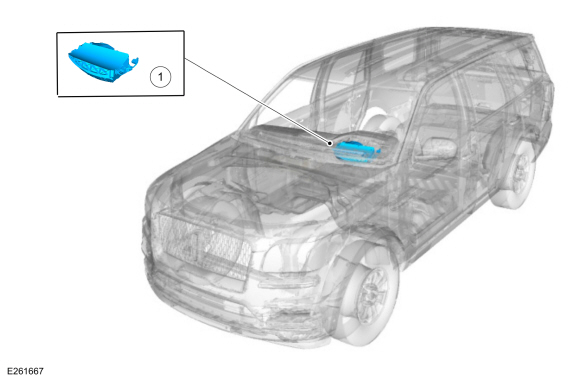
Lincoln Navigator: Collision Warning and Collision Avoidance System / Collision Warning and Collision Avoidance System - Component Location. Description and Operation
| Item | Description |
|---|---|
| 1 | HUD module |

 Collision Warning and Collision Avoidance System - System Operation and Component Description. Description and Operation
System Operation
ACC With Pre-Collision Assist
E370171
*.sttxt {
visibility: hidden;
}
*.stcallout {
visibility: visible;
}
1
ACM
2
HUD
3
CCM
4
IPC
5
BCM
..
Other information:
Lincoln Navigator 2018-2026 Workshop Manual: Air Conditioning (A/C) System Leak Test Using Forming Gas. General Procedures
Special Tool(s) / General Equipment Forming Gas Pressure Gauge and Leak Detector Materials Name Specification Forming Gas - Leak detection All vehicles NOTE: Use a Rotunda-approved Forming Gas A/C System Dealership Leak Detection Service Kit that meets SAE J2790. Recover the refrigerant. Refer to the appropriate Recovery p..
Lincoln Navigator 2018-2026 Workshop Manual: Fuel Filler Door. Removal and Installation
Removal Open the fuel filler door. Using a screwdriver, push the retaining tab and slide the fuel filler door and remove. Installation To install, reverse the removal procedure. ..
Categories
- Manuals Home
- 4th Gen Lincoln Navigator Service Manual (2018 - 2026)
- Power Running Board (PRB). Diagnosis and Testing
- Rear View Mirrors - System Operation and Component Description. Description and Operation
- Head Up Display (HUD) Module Calibration. General Procedures
- Body Control Module (BCM). Removal and Installation
- Remote Function Actuator (RFA) Module. Removal and Installation
Wheel to Hub Runout Minimization. General Procedures
Check
NOTE: Wheel-to-hub optimization is important. Clearance between the wheel and hub can be used to offset or neutralize the Road Force® or run-out of the wheel and tire assembly. For every 0.001 inch of wheel-to-hub clearance, the Road Force® can be affected between 1 and 3 pounds depending on the tire stiffness.
NOTE: The example below illustrates how the clearance between the wheel and the hub can be used to offset the high spot of radial run-out or Road Force®. Following the procedure will make sure of the best optimization.
Position the wheel and tire assembly on the vehicle so that the high spot location of radial run-out or Road Force® is at the 6 o'clock position and