Lincoln Navigator: Hydraulic Brake Actuation / Brake Pedal and Bracket. Removal and Installation
Removal
NOTE: Removal steps in this procedure may contain installation details.
NOTE: Adjustable brake pedal and bracket shown, fixed brake pedal and bracket similar.
Vehicles equipped with adjustable pedals
-
NOTICE: The brake pedal and the accelerator pedal must be in the same position when installing a new cable or a new pedal. The pedals must be all the way forward or all the way rearward or damage to components may occur.
Move the pedals to the full forward (away from the driver) position.
All vehicles
-
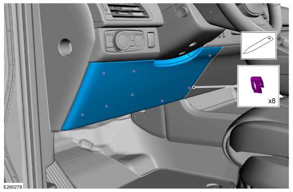
Deatch the clips and remove the steering column opening cover.
 |
-
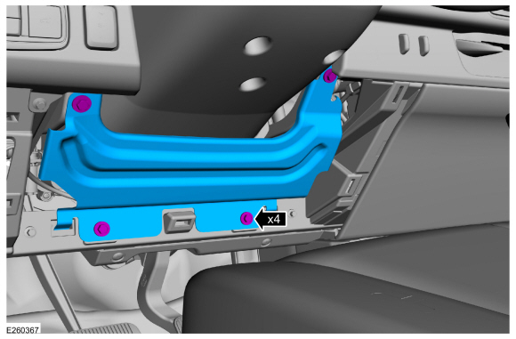
Remove the bolts and the steering column opening trim panel reinforcement.
Torque: 80 lb.in (9 Nm)
 |
Vehicles equipped with adjustable pedals
-
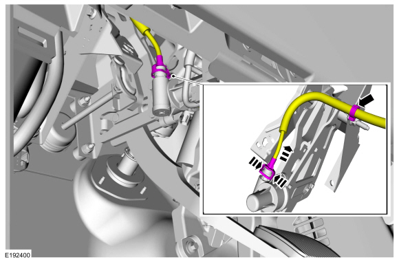
Disconnect the adjustable pedal motor drive cable from the adjustable brake pedal drive.
 |
All vehicles
-
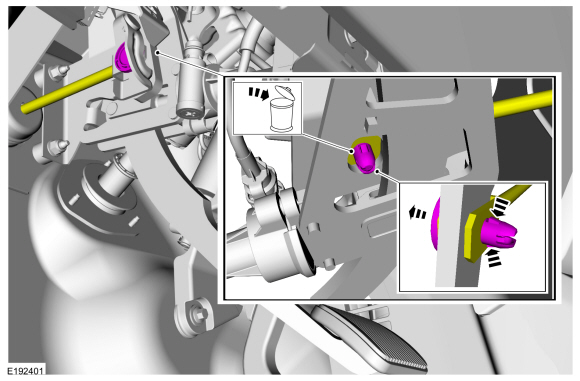
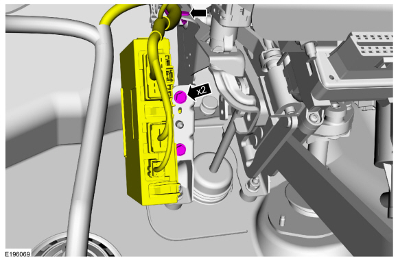
NOTICE: Do not service the brake pedal without first removing the stoplamp switch. Remove this switch with the brake pedal in the at-rest position. Attempting to remove the switch when the plunger is extended (during pedal apply) results in damage to the switch.
Remove the stoplamp switch.
-
Remove the brake pedal clevis pin, and disconnect
the brake booster push rod from the brake pedal arm. Discard the brake
pedal clevis pin.
 |
-
If equipped, remove the 2 bolts and the trailer tow lighting module.
Torque: 106 lb.in (12 Nm)
 |
-
-
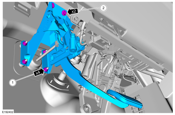
NOTE: Tighten the 4 brake booster-to-pedal bracket nuts in a cross-pattern.
Remove the 4 brake booster-to-pedal bracket nuts.
Torque: 18 lb.ft (25 Nm)
-
Remove the 2 brake pedal bracket bolts and while
pushing the brake booster towards the engine compartment, remove the
brake pedal and bracket.
Torque: 18 lb.ft (25 Nm)
-
 |
Installation
All vehicles
-
NOTICE: Do not press, pull or otherwise move the brake pedal while installing the stoplamp switch. Install this switch with the booster push rod attached to the brake pedal and with the brake pedal in the at-rest position. Installing this switch with the pedal in any other position results in incorrect adjustment and damages the switch.
To install, reverse the removal procedure.
Vehicles equipped with adjustable pedals
-
Index the pedal assemblies.
Refer to: Adjustable Pedal Indexing (206-06 Hydraulic Brake Actuation, General Procedures).
 Adjustable Pedal Indexing. General Procedures
NOTICE:
The adjustable pedal system must be indexed whenever the brake
pedal assembly or accelerator pedal assembly is installed or damage to
the components may result...
 Brake Pedal Control Switch. Removal and Installation
Removal
NOTE:
Removal steps in this procedure may contain installation details.
Detach the clips and remove the lower steering column opening cover...
Other information:
Lincoln Navigator 2018-2026 Workshop Manual: Rear Lamp Mounting Panel. Removal and Installation
Special Tool(s) / General Equipment 6.5 mm Drill Bit Polydrive Bit Socket Self-Piercing Rivet (SPR) Remover/Installer Belt Sander Blind Rivet Gun Locking Pliers Materials Name Specification Metal Bonding AdhesiveTA-1, TA-1-B, 3M™ 08115, LORD Fusor® 108B, Henkel Teroson EP 5055 - Flexible Foam Repair3M™ ..
Lincoln Navigator 2018-2026 Workshop Manual: High Mounted Stoplamp. Removal and Installation
Removal Remove the rear spoiler. Refer to: Rear Spoiler (501-08 Exterior Trim and Ornamentation, Removal and Installation). Remove the bolts and the high mounted stop lamp assembly. Disconnect the electrical connector. Installation To install, reverse the removal procedure. ..
Categories
- Manuals Home
- 4th Gen Lincoln Navigator Service Manual (2018 - 2026)
- Brake Service Mode Activation and Deactivation. General Procedures
- Front Bumper Cover. Removal and Installation
- Body and Paint
- Body Control Module (BCM). Removal and Installation
- Identification Codes. Description and Operation
Rear Stabilizer Bar Link. Removal and Installation
Removal
NOTE: Removal steps in this procedure may contain installation details.
With the vehicle in NEUTRAL, position it on a hoist.Refer to: Jacking and Lifting (100-02 Jacking and Lifting, Description and Operation).
NOTE: Use the hex-holding feature to prevent the stud from turning while removing the nut.
Remove and discard the 2 rear stabilizer bar link nuts and remove the rear stabilizer bar link.Torque: 46 lb.ft (63 Nm)
