Lincoln Navigator: Side Panel Sheet Metal Repairs / A-Pillar Outer Panel. Removal and Installation
Special Tool(s) /
General Equipment
| 6.5 mm Drill Bit |
| Spherical Cutter |
| Polydrive Bit Socket |
| Self-Piercing Rivet (SPR) Remover/Installer |
| Belt Sander |
| Blind Rivet Gun |
| Hot Air Gun |
| Air Body Saw |
| MIG/MAG Welding Equipment |
| Locking Pliers |
Materials
| Name |
Specification |
Metal Bonding Adhesive
TA-1, TA-1-B, 3M™ 08115, LORD Fusor® 108B, Henkel Teroson EP 5055 |
-
|
Seam Sealer
TA-2-B, 3M™ 08308, LORD Fusor® 803DTM |
-
|
Removal
NOTICE:
Body side sectioning is prohibited within 50mm of door hinge, door striker and restraints anchoring points.
-
Depower the SRS .
Refer to: Supplemental Restraint System (SRS) Depowering (501-20B Supplemental Restraint System, General Procedures).
-
Verify the vehicle is dimensionally correct.
Refer to: Body and Frame (501-26 Body Repairs - Vehicle Specific Information and Tolerance Checks, Description and Operation).
-
Remove the front door.
Refer to: Front Door (501-03 Body Closures, Removal and Installation).
-
Remove the front fender.
Refer to: Fender (501-02 Front End Body Panels, Removal and Installation).
-
Remove the front door hinges.
-
Remove the windshield.
Refer to: Fixed Glass (501-11 Glass, Frames and Mechanisms, General Procedures).
-
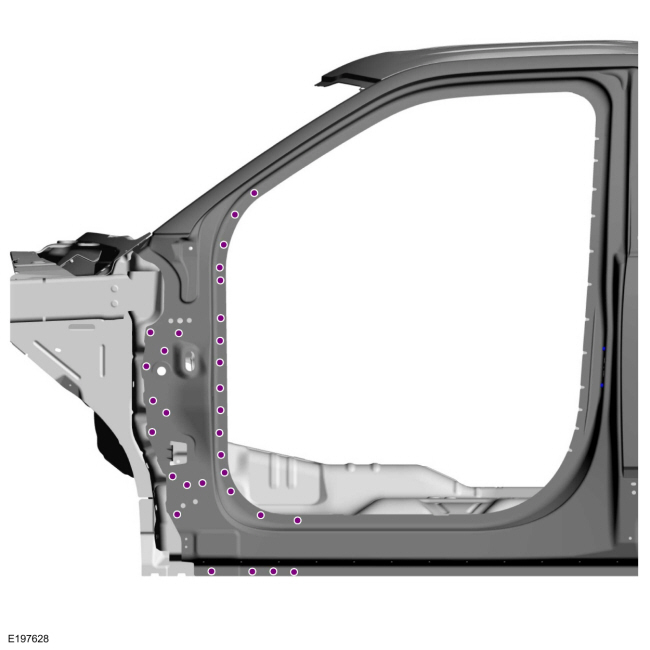
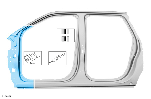
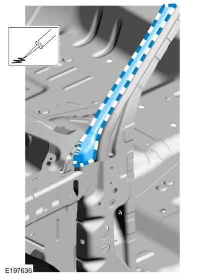
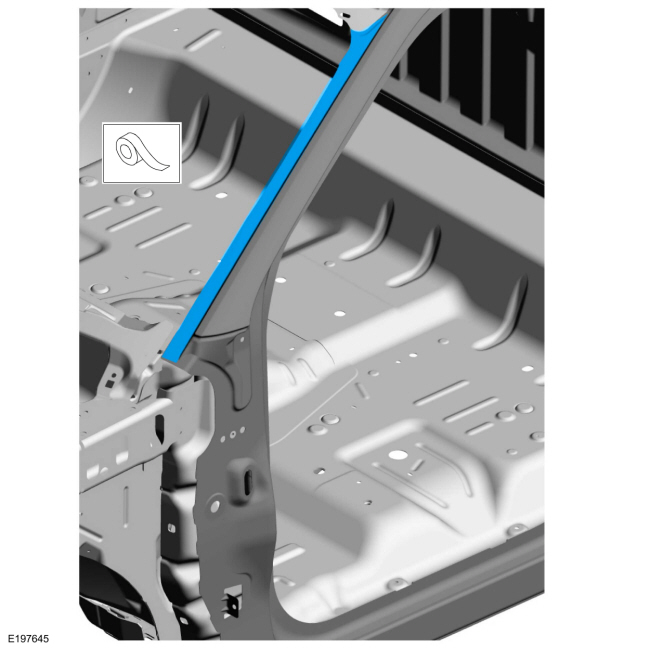
Outer panel only
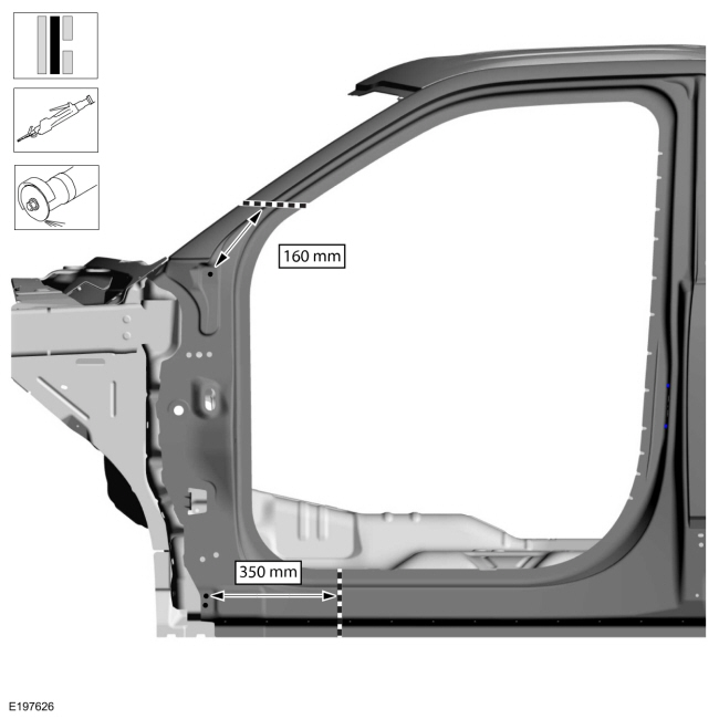
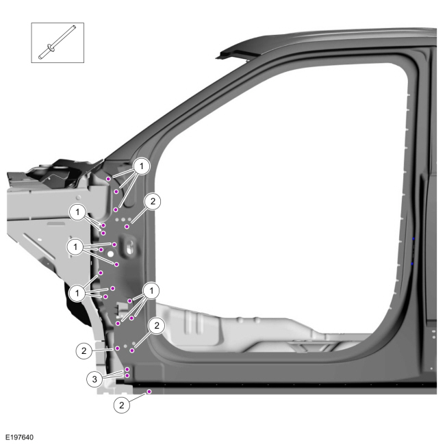
Carefully cut the panel as indicated.
Use the General Equipment: Air Body Saw
Use the General Equipment: Spherical Cutter
-
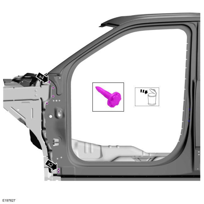
Remove and discard the FDS fasteners.
Use the General Equipment: Polydrive Bit Socket
-
Remove the SPR fasteners.
Use the General Equipment: Self-Piercing Rivet (SPR) Remover/Installer
Use the General Equipment: Belt Sander
-
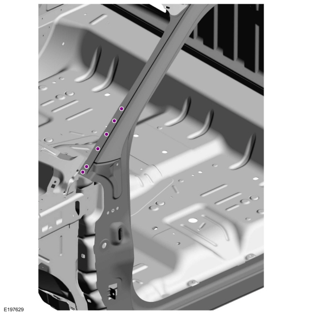
Remove the SPR fasteners in the windshield opening.
Use the General Equipment: Self-Piercing Rivet (SPR) Remover/Installer
Use the General Equipment: Belt Sander
-
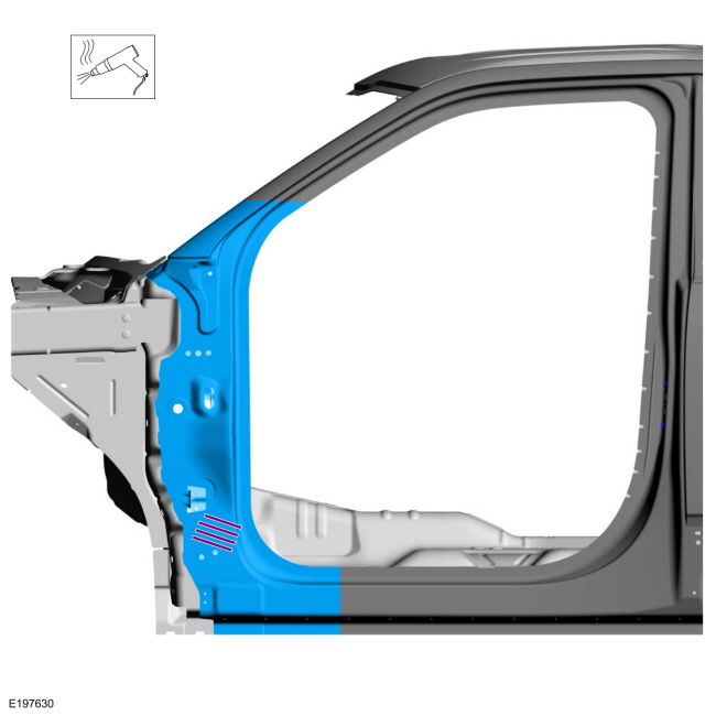
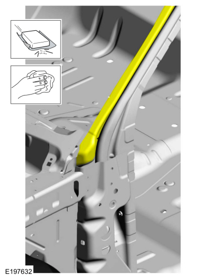
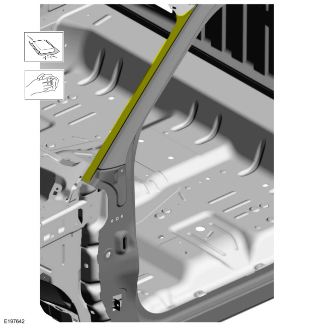
NOTE:
Aluminum body panels are highly receptive to heat
transfer. With the extensive use of structural adhesives and
non-structural sealers used in vehicle construction, the potential of
heat transfer could impact adhesives and sealers in non-associated
panels during the repair process. Many repairs areas that utilize
structural adhesive may be separated after fastener removal by using a
panel chisel along the joint/flange. Using heat not exceeding 425° F to
loosen a bonded panel should only be done when all panels in the joint
will be replaced and new adhesive applied.
Break the adhesive bond and remove the outer side section.
Use the General Equipment: Hot Air Gun
Installation
NOTICE:
Body side sectioning is prohibited within 50mm of door hinge, door striker and restraints anchoring points.
NOTE:
Do not install SPR fasteners directly in old SPR fastener location. SPR
fasteners must be installed adjacent to the original location matching
original quantity.
NOTE:
Solid rivets or blind rivet fasteners may be used in place of SPR fasteners after enlarging existing holes to 6.5 mm.
-
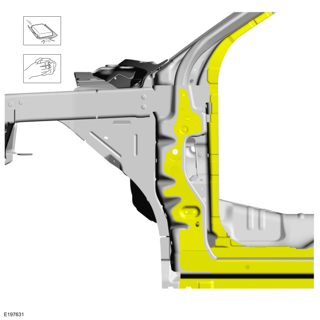
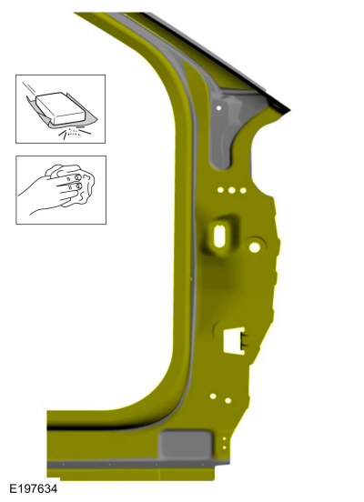
Sand with 80 grit sand paper to remove old adhesive and clean.
-
Sand with 80-120 grit sand paper to remove old adhesive from windshield opening and clean.
-
Cut service panel to fit.
Use the General Equipment: Air Body Saw
Use the General Equipment: Spherical Cutter
-
NOTE:
The use of a backer plate when creating butt weld joints will produce a stronger and more uniform repair.
Create a backer plate from an unused portion of the old
body panel or service replacement panel and install on the vehicle at
each sectioning joint.
Refer to: Joining Techniques (501-25 Body Repairs - General Information, General Procedures).
-
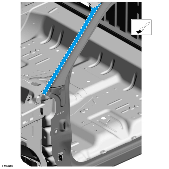
Sand using 80 grit sand paper to remove e-coat and clean as indicated.
-
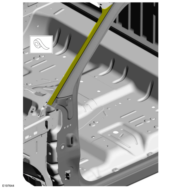
Apply adhesive.
Material: Metal Bonding Adhesive
/ TA-1, TA-1-B, 3M™ 08115, LORD Fusor® 108B, Henkel Teroson EP 5055
-
Apply adhesive to the windshield opening.
Material: Metal Bonding Adhesive
/ TA-1, TA-1-B, 3M™ 08115, LORD Fusor® 108B, Henkel Teroson EP 5055
-
Install the service panel and clamp in position.
Use the General Equipment: Locking Pliers
-
Complete backer plate installation to replacement panel.
Refer to: Joining Techniques (501-25 Body Repairs - General Information, General Procedures).
-
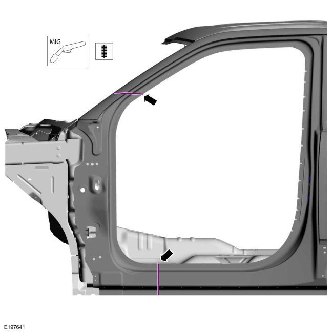
Seam weld sectioning joints using a MIG welder set up for aluminum welding.
Use the General Equipment: MIG/MAG Welding Equipment
-
NOTE:
Do not install SPR fasteners directly in old SPR fastener location. SPR
fasteners must be installed adjacent to the original location matching
original quantity.
NOTE:
Solid rivets or blind rivet fasteners may be used in place of SPR fasteners after enlarging existing holes to 6.5 mm.
Install fasteners in windshield opening.
|
Item
|
SPR Number
|
SPR Code
|
Henrob® Mandrel
|
Pro-Spot® Mandrel
|
Blind Rivet
|
Solid Rivet
|
Rivnut®
|
|
1
|
W708713-S900
|
AS
|
DZ09-025/H
|
SA-0400-SA-0402
|
-
|
W790377-S900
|
-
|
Refer to: Joining Techniques (501-25 Body Repairs - General Information, General Procedures).
Use the General Equipment: Self-Piercing Rivet (SPR) Remover/Installer
 |
|
-
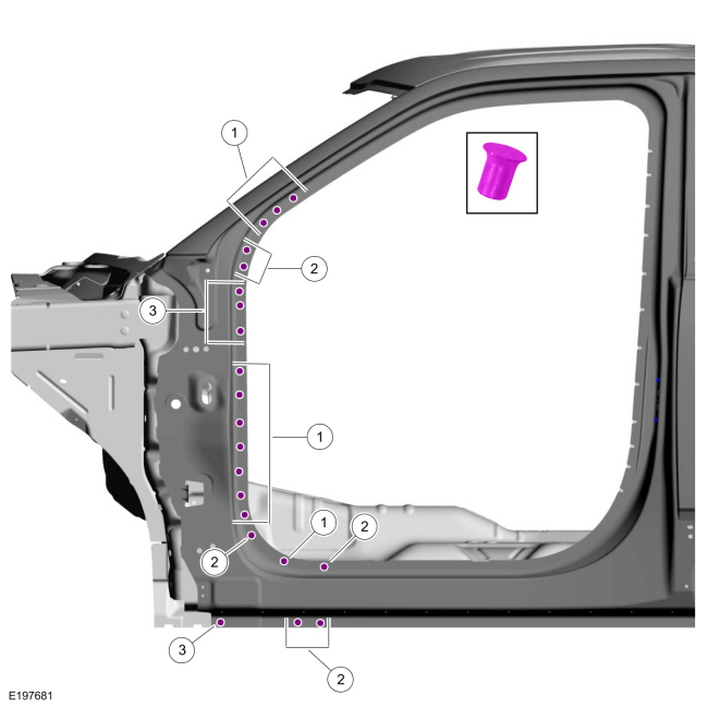
NOTE:
Do not install SPR fasteners directly in old SPR fastener location. SPR
fasteners must be installed adjacent to the original location matching
original quantity.
NOTE:
Solid rivets or blind rivet fasteners may be used in place of SPR fasteners after enlarging existing holes to 6.5 mm.
Install fasteners in body side.
|
Item
|
SPR Number
|
SPR Code
|
Henrob® Mandrel
|
Pro-Spot® Mandrel
|
Blind Rivet
|
Solid Rivet
|
Rivnut®
|
|
1
|
W708713-S900
|
AS
|
DZ09-025/H
|
SA-0400/SA-0401
|
-
|
W790376-S900
|
-
|
|
2
|
W717186-S900
|
EN
|
DG11-220/H
|
SA-0400/SA-0401
|
-
|
W790377-S900
|
-
|
|
3
|
W710246-S900
|
BN
|
DP10-200/H
|
SA-0400/SA-0402
|
-
|
W790377-S900
|
-
|
Use the General Equipment: Self-Piercing Rivet (SPR) Remover/Installer
-
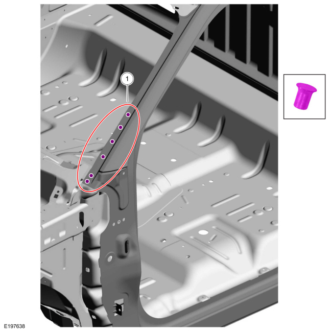
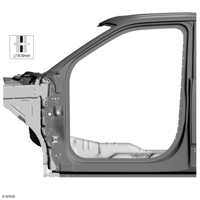
Drill 6.5 mm holes as indicated.
Use the General Equipment: 6.5 mm Drill Bit
-
NOTE:
Do not install SPR fasteners directly in old SPR fastener location. SPR
fasteners must be installed adjacent to the original location matching
original quantity.
NOTE:
Solid rivets or blind rivet fasteners may be used in place of SPR fasteners after enlarging existing holes to 6.5 mm.
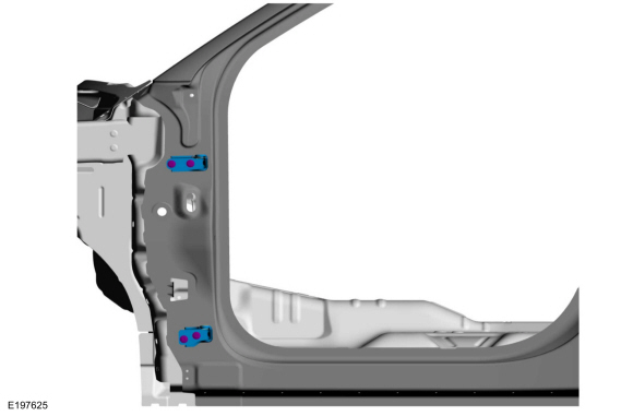
Install fasteners.
|
Item
|
SPR Number
|
SPR Code
|
Henrob® Mandrel
|
Pro-Spot® Mandrel
|
Blind Rivet
|
Solid Rivet
|
Rivnut®
|
|
1
|
-
|
-
|
-
|
-
|
W707638-S900C
|
-
|
-
|
|
2
|
-
|
-
|
-
|
-
|
W708777-S900C
|
-
|
-
|
|
3
|
-
|
-
|
-
|
-
|
W702554-S900C
|
-
|
-
|
Use the General Equipment: Blind Rivet Gun
-
Metal finish all seams using typical aluminum metal finishing techniques and a fiber-based body filler.
Refer to: Special Repair Considerations for Aluminum Repairs (501-25
Body Repairs - General Information, Description and Operation).
-
Sand the windshield opening channel and clean.
-
Prime the windshield opening channel using a Ford approved epoxy primer.
-
Mask the glass channel as indicated.
-
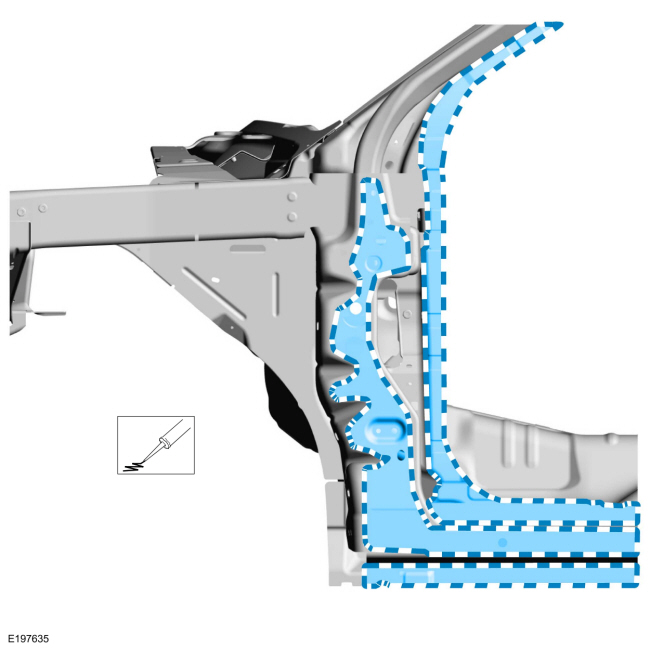
NOTE:
Apply seam sealer after priming the area.
Sealing work: All areas must be sealed to production level.
Material: Seam Sealer
/ TA-2-B, 3M™ 08308, LORD Fusor® 803DTM
-
Prime and refinish the entire repair area using a Ford approved paint system and typical refinishing techniques.
-
Remove the masking from the windshield opening channel.
-
Install the windshield.
Refer to: Fixed Glass (501-11 Glass, Frames and Mechanisms, General Procedures).
-
Install the front door hinges to the body.
Torque:
24 lb.ft (32 Nm)
-
Install the front door.
Refer to: Front Door (501-03 Body Closures, Removal and Installation).
-
Install the front fender.
Refer to: Fender (501-02 Front End Body Panels, Removal and Installation).
-
Align the front door.
Refer to: Front Door Alignment (501-03 Body Closures, General Procedures).
-
Repower the SRS
Refer to: Supplemental Restraint System (SRS) Repowering (501-20B Supplemental Restraint System, General Procedures).
Special Tool(s) /
General Equipment
6.5 mm Drill Bit
Polydrive Bit Socket
Self-Piercing Rivet (SPR) Remover/Installer
Belt Sander
Blind Rivet Gun
Hot Air Gun
Locking Pliers
Materials
Name
Specification
Metal Bonding AdhesiveTA-1, TA-1-B, 3M™ 08115, LORD Fusor® 108B, Henkel Teroson EP 5055
-
Flexib..
Other information:
Diagnostic Trouble Code (DTC) Chart
Diagnostics in this manual assume a certain skill level and knowledge of Ford-specific diagnostic practices. REFER to: Diagnostic Methods (100-00 General Information, Description and Operation).
Module
DTC
Description
Action
BCM
B1A85:11
Ambient Light Sensor: Circuit Short To Ground
GO to Pinpoint Test A
BCM
B1A85:13
..
Diagnostic Trouble Code (DTC) Chart
Diagnostics in this manual assume a certain skill level and knowledge of Ford-specific diagnostic practices. REFER to: Diagnostic Methods (100-00 General Information, Description and Operation).
Module
DTC
Description
Action
DCMR
P0745:12
Pressure Control Solenoid A: Circuit Short To Battery
GO to Pinpoint Test E
DCMR
P..


 A-Pillar Outer Panel Section and Reinforcement. Removal and Installation