Lincoln Navigator: Rear Suspension / Upper Trailing Arm. Removal and Installation
Removal
NOTICE: Suspension fasteners are critical parts that affect the performance of vital components and systems. Failure of these fasteners may result in major service expense. Use the same or equivalent parts if replacement is necessary. Do not use a replacement part of lesser quality or substitute design. Tighten fasteners as specified.
-
Remove the wheel and tire.
Refer to: Wheel and Tire (204-04A Wheels and Tires, Removal and Installation).
-
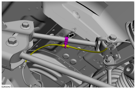
Detach the wiring retainer and keep aside the rear wheel speed sensor wire.
 |
-
-
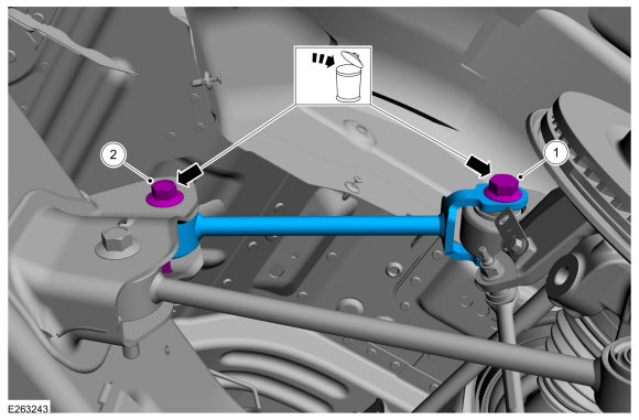
Remove and discard the upper trailing arm-to-wheel knuckle bolt.
-
Remove and discard the upper trailing arm-to-frame bolt and flagnut.
-
Remove and discard the upper trailing arm-to-wheel knuckle bolt.
 |
Installation
-
NOTE: Only tighten the nut and bolts finger tight at this stage.
-
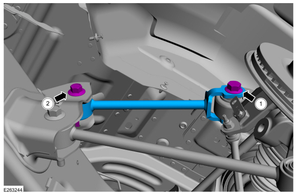
Install the new upper trailing arm-to-wheel knuckle bolt.
-
Install the new upper trailing arm-to-frame bolt and flagnut.
-
Install the new upper trailing arm-to-wheel knuckle bolt.
 |
-
Attach the wiring retainer and the rear wheel speed sensor wire to the upper trailing arm.
|
-
Install the wheel and tire.
Refer to: Wheel and Tire (204-04A Wheels and Tires, Removal and Installation).
- Lower the vehicle so that the weight of the vehicle is on the wheel and tire assemblies.
-
-
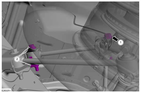
Tighten the new upper trailing arm-to-wheel knuckle bolt.
Torque: 184 lb.ft (250 Nm)
-
Tighten the new upper trailing arm-to-frame bolt and flagnut.
Torque: 203 lb.ft (275 Nm)
-
Tighten the new upper trailing arm-to-wheel knuckle bolt.
 |
 Upper Arm. Removal and Installation
Special Tool(s) /
General Equipment
204-592/1Adapter for 204-592
Removal
NOTICE:
Suspension fasteners are critical parts that affect the
performance of vital components and systems...
 Wheel Bearing and Wheel Hub. Removal and Installation
Removal
NOTICE:
Suspension fasteners are critical parts that affect the
performance of vital components and systems. Failure of these fasteners
may result in major service expense...
Other information:
Lincoln Navigator 2018-2026 Workshop Manual: Fog Lamps. Diagnosis and Testing
Diagnostic Trouble Code (DTC) Chart Diagnostics in this manual assume a certain skill level and knowledge of Ford-specific diagnostic practices. REFER to: Diagnostic Methods (100-00 General Information, Description and Operation). Module DTC Description Action BCM B1147:11 Left Front Fog Lamps: Circuit Short To Ground GO to Pinpoint Test A BCM B1147:15 ..
Lincoln Navigator 2018-2026 Workshop Manual: Radiator. Removal and Installation
Removal NOTE: Removal steps in this procedure may contain installation details. Drain the cooling system. Refer to: Engine Cooling System Draining, Vacuum Filling and Bleeding (303-03 Engine Cooling - 3.5L EcoBoost (272kW/370PS), General Procedures). Remove the cooling fan motor and shroud. Refer to: Cooling Fan Motor and Shroud (303-03 Engine Co..
Categories
- Manuals Home
- 4th Gen Lincoln Navigator Service Manual (2018 - 2026)
- Body and Paint
- Power Running Board (PRB). Diagnosis and Testing
- Remote Function Actuator (RFA) Module. Removal and Installation
- Head Up Display (HUD) Module Calibration. General Procedures
- Body Control Module (BCM). Removal and Installation
Front Driveshaft. Removal and Installation
Special Tool(s) / General Equipment
Crimping ToolMaterials
Name Specification Motorcraft® Premium Long-Life GreaseXG-1-E1 ESA-M1C75-B
Removal
With the vehicle in NEUTRAL, position the vehicle on a hoist.Refer to: Jacking and Lifting (100-02 Jacking and Lifting, Description and Operation).
Remove the bolts and the transmission shield.