Lincoln Navigator: Automatic Transmission - 10-Speed Automatic Transmission – 10R80 / Torque Converter. Description and Operation
Overview
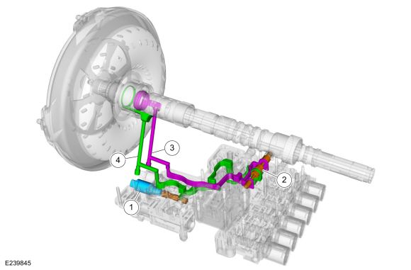
| Item | Description |
| 1 | TCC solenoid |
| 2 | TCC regulator valve assembly |
| 3 | TCC apply circuit |
| 4 | TCC release circuit |
Torque Converter Hydraulic Circuits (TCC Released)
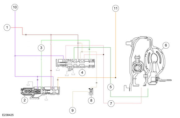
| Item | Description |
| 1 | LPC pressure |
| 2 | TCC solenoid |
| 3 | TCC control pressure |
| 4 | TCC regulator valve |
| 5 | TCC release pressure |
| 6 | TCC |
| 7 | TCC exhaust to TCC regulator valve |
| 8 | Torque converter anti-drainback valve |
| 9 | TCC exhaust |
| 10 | Pump output |
| 11 | Decreased pressure from main requlator valve |
Line pressure fills the converter feed circuit with fluid up to 1,103 kPa (160 psi). The converter feed blow off valve prevents excessive pressure from reaching the torque converter. When the TCC solenoid is commanded off, the TCC regulator valve connects the converter feed circuit to the converter release circuit and fluid flows into the torque converter. Fluid exits the torque converter in the converter apply circuit. The TCC regulator valve connects the converter apply circuit and the from converter circuit. The from converter circuit flows past the converter anti-drainback valve and on to the cooler bypass valve.
Torque Converter Hydraulic Circuits (TCC Applied)
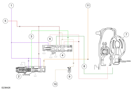
| Item | Description |
| 1 | Pump output |
| 2 | TCC solenoid |
| 3 | TCC control pressure |
| 4 | TCC regulator valve |
| 5 | LPC pressure |
| 6 | TCC apply pressure |
| 7 | TCC |
| 8 | TCC exhaust to TCC regulator valve |
| 9 | Torque converter anti-drainback valve |
| 10 | TCC exhaust |
| 11 | Decreased pressure from main requlator valve |
To apply to TCC , the TCC solenoid directs TCC control pressure to the TCC regulator valve, moving the valve to the left against the spring pressure. The TCC regulator valve is positioned to connect pump output to the converter apply circuit. Fluid in the apply circuit is routed to the converter and applies the TCC . Fluid exits the torque converter in the converter release circuit. The TCC regulator valve connects the converter release to exhaust and fluid returns to the sump.
When the TCC regulator valve is in the TCC applied position, the converter feed circuit is connected to the from converter circuit allowing continued fluid flow to the cooler bypass valve.
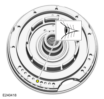
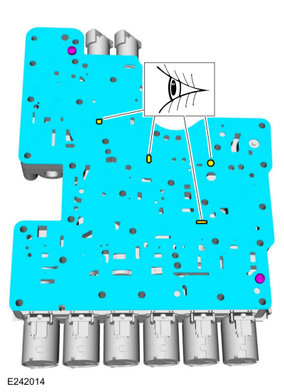
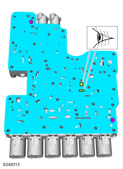
Torque Converter Hydraulic Passages (TCC Released)
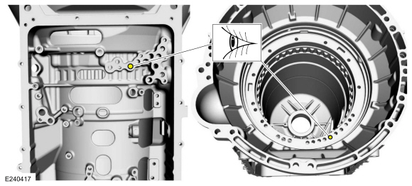
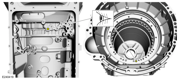
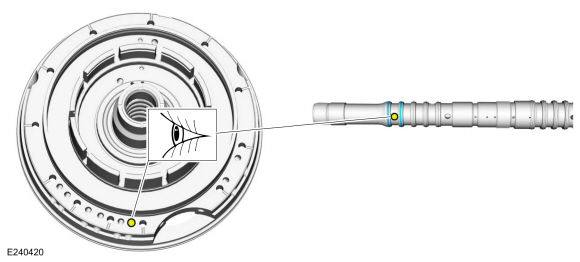
Torque Converter Hydraulic Passages (TCC Applied)
 Low One-Way Clutch Assembly. Description and Operation
One-Way Clutch (OWC) Exploded View
Item
Description
1
Front support assembly
2
One-Way Clutch (OWC)
3
Sun gear No...
 Main Control Valve Body. Description and Operation
Item
Description
1
Internal wiring harness retaining bolt
2
Internal wiring harness
3
Park lock pawl solenoid
4
Solenoid retaining plate bolts
5
Solenoid retaining plate
6
TCC solenoid
..
Other information:
Lincoln Navigator 2018-2026 Workshop Manual: Battery. Diagnosis and Testing
General Equipment Diagnostic Battery Charger Use Ford approved battery test equipment listed in the Ford Warranty and Policy Manual. Diagnostics in this manual assume a certain skill level and knowledge of Ford-specific diagnostic practices. REFER to: Diagnostic Methods (100-00 General Information, Description and Operation). Diagnostic Trouble Code (DTC) Chart..
Lincoln Navigator 2018-2026 Workshop Manual: Cruise Control - System Operation and Component Description. Description and Operation
System Diagram *.sttxt { visibility: hidden; } *.stcallout { visibility: visible; } 1 Electric Brake Booster (EBB) E361930 2 IPC 3 Accelerator Pedal 4 Deactivator Switch 5 Stoplamp Switch 6 SCCM ..
Categories
- Manuals Home
- 4th Gen Lincoln Navigator Service Manual (2018 - 2026)
- Body Control Module (BCM). Removal and Installation
- Identification Codes. Description and Operation
- Brake Service Mode Activation and Deactivation. General Procedures
- Power Running Board (PRB). Diagnosis and Testing
- Transmission Fluid Level Check. General Procedures
Wheel to Hub Runout Minimization. General Procedures
Check
NOTE: Wheel-to-hub optimization is important. Clearance between the wheel and hub can be used to offset or neutralize the Road Force® or run-out of the wheel and tire assembly. For every 0.001 inch of wheel-to-hub clearance, the Road Force® can be affected between 1 and 3 pounds depending on the tire stiffness.
NOTE: The example below illustrates how the clearance between the wheel and the hub can be used to offset the high spot of radial run-out or Road Force®. Following the procedure will make sure of the best optimization.
Position the wheel and tire assembly on the vehicle so that the high spot location of radial run-out or Road Force® is at the 6 o'clock position and