Lincoln Navigator: Rear Drive Axle/Differential - Vehicles With: Ford 9.75 Inch Ring Gear / Ring Gear Backlash Adjustment. General Procedures
Special Tool(s) / General Equipment
 |
205-220 Installer, Differential Shim TKIT-1985-FH |
 |
307-003
(T57L-500-B)
Holding Fixture, Transmission |
| Dial Indicator | |
| Copper Hammer | |
Adjustment
-
Remove the rear axle assembly.
Refer to: Axle Assembly (205-02 Rear Drive Axle/Differential - Vehicles With: Ford 9.75 Inch Ring Gear, Removal and Installation).
-
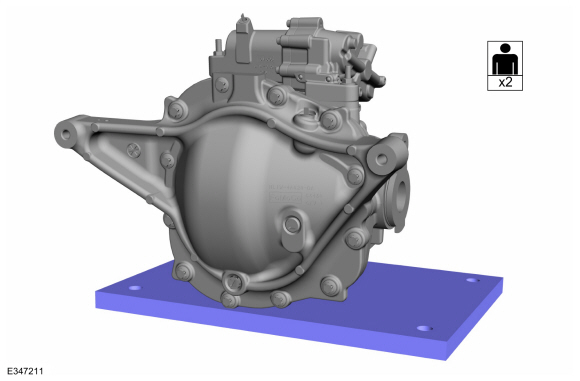
NOTE: This step requires the aid of another technician.
Transfer the rear axle assembly from the transmission jack to a workbench.
 |
-
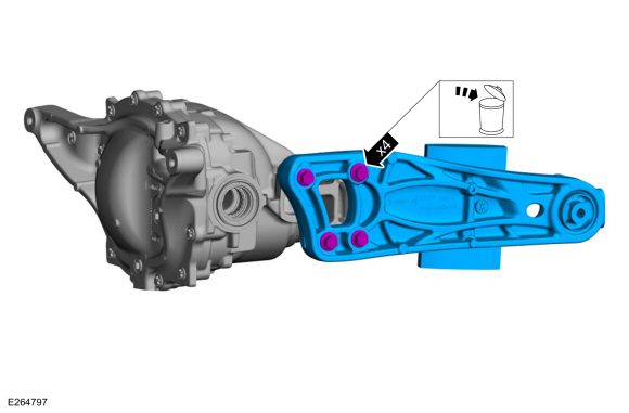
Remove and discard the torque arm bolts and remove the torque arm from the rear axle housing.
 |
-
Remove and discard the torque arm locating sleeves.
 |
-
Remove the differential housing cover.
Refer to: Differential Housing Cover (205-02 Rear Drive Axle/Differential - Vehicles With: Ford 9.75 Inch Ring Gear, Removal and Installation).
-
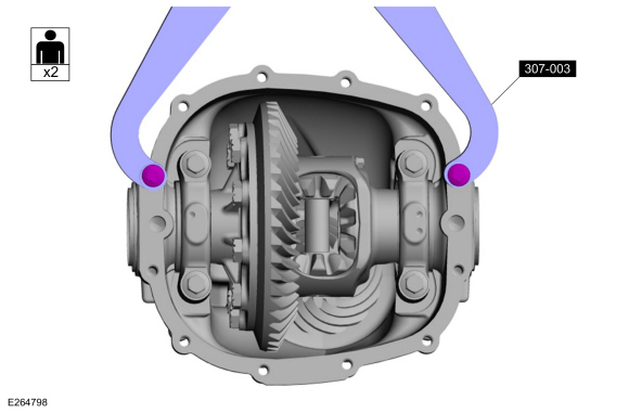
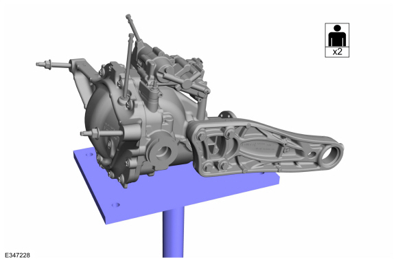
NOTE: This step requires the aid of another technician.
Using the Transmission Holding Fixture, mount the differential housing to a work bench.
Use Special Service Tool: 307-003 (T57L-500-B) Holding Fixture, Transmission.
 |
-
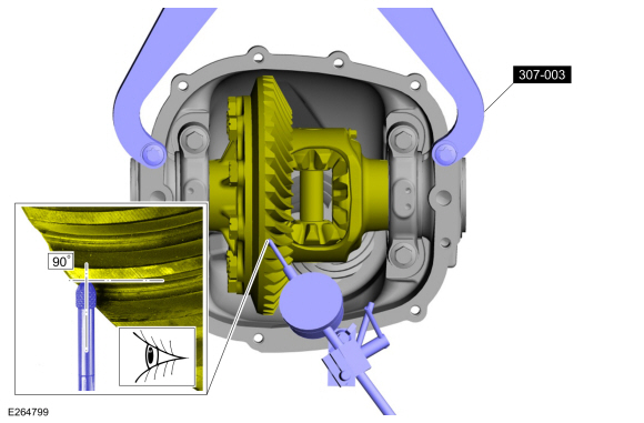
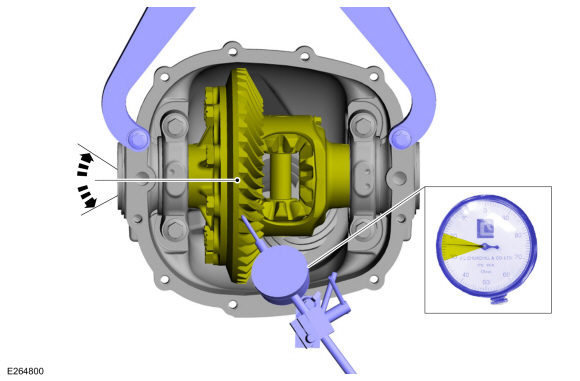
Install the dial indicator gauge with holding fixture,
with the dial indicator at a 90 degree angle from the ring gear tooth.
Use Special Service Tool: 307-003 (T57L-500-B) Holding Fixture, Transmission.
Use the General Equipment: Dial Indicator
 |
-
Using the dial indicator check the ring gear backlash.
Rotate the ring gear and carrier back and forth through the free play
only.
Refer to: Specifications (205-02 Rear Drive Axle/Differential - Ford 9.75 Inch Ring Gear) .
Use the General Equipment: Dial Indicator
 |
-
-
If a zero backlash condition occurs or the backlash is not within specification, proceed to Step 9.
-
If the backlash is within specification, proceed to Step 20.
-
If a zero backlash condition occurs or the backlash is not within specification, proceed to Step 9.
-
-
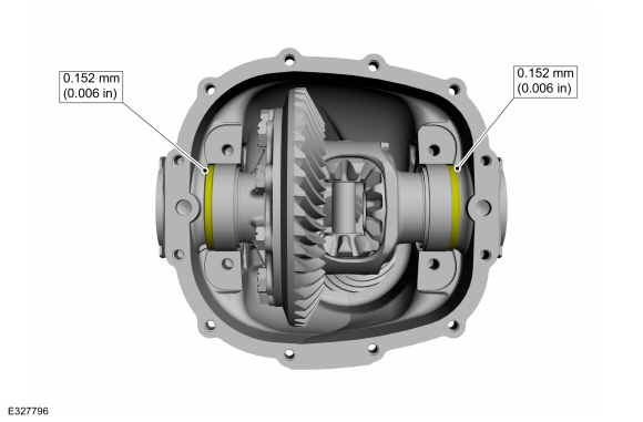
To correct for high or low backlash, increase the
thickness of one differential bearing shim and decrease the thickness of
the other differential bearing shim by the same amount.
-
If a zero backlash condition had occurred, add 0.50 mm (0.020 in) to
the RH side shim and subtract 0.50 mm (0.020 in) from the LH side shim
to allow a backlash indication. Recheck backlash.
-
Using the backlash chart, determine the thickness of differential shim needed:
Refer to: Specifications (205-02 Rear Drive Axle/Differential - Ford 9.75 Inch Ring Gear) .
-
To correct for high or low backlash, increase the
thickness of one differential bearing shim and decrease the thickness of
the other differential bearing shim by the same amount.
-
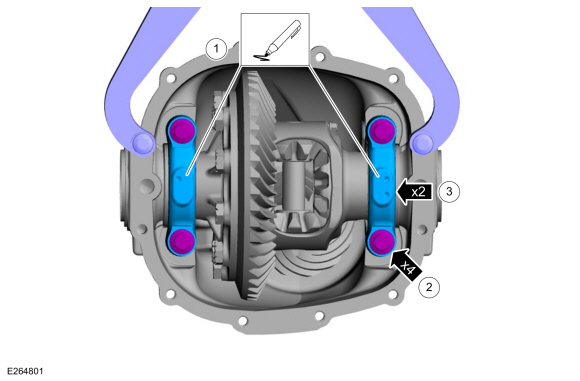
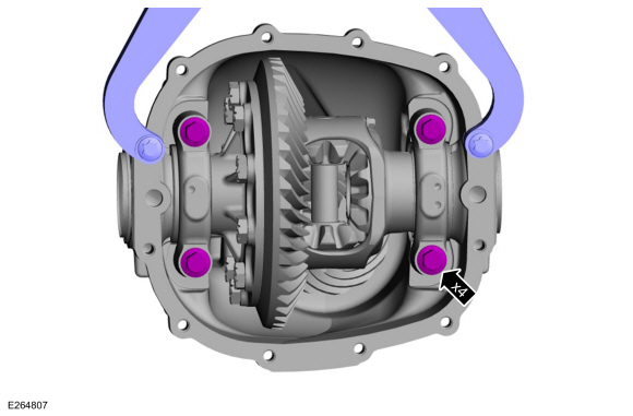
NOTE: The differential bearing caps and differential bearing cap bolts need to be installed in the same location as removed.
-
Mark the differential bearing caps.
-
Remove the differential bearing cap bolts.
-
Remove the differential bearing caps.
-
Mark the differential bearing caps.
 |
-
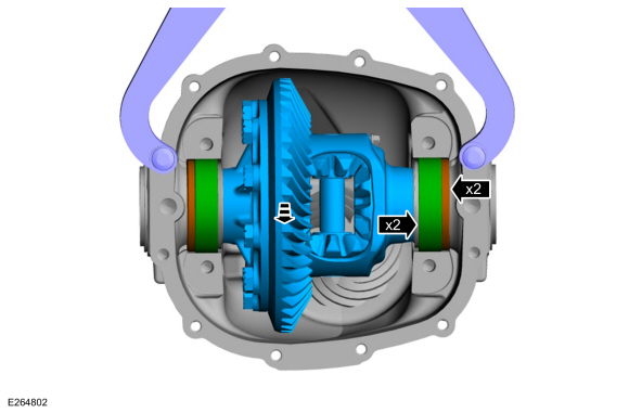
Remove the differential carrier, differential carrier bearing cups and the differential shims.
 |
-
NOTE: Have the selected shims available at this time. It will be required to hold the differential carrier and the differential carrier bearing cups in until shims are installed.
Install the differential carrier and the differential carrier bearing cups.
 |
-
To establish differential bearing preload, increase both LH and RH differential bearing shim size by the thickness shown.
 |
-
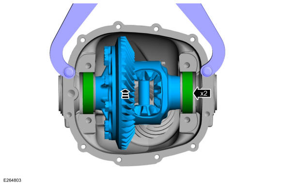
NOTE: Differential bearing shims are to be installed with the chamfer facing outboard.
-
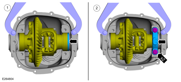
Install the RH selected ring gear back lash shim.
-
NOTE: The differential bearing cap bolts should only be finger tight at this time.
Position the differential to the RH side of the differential housing. Install the RH differential bearing cap and the differential bearing cap bolts.
-
Install the RH selected ring gear back lash shim.
 |
-
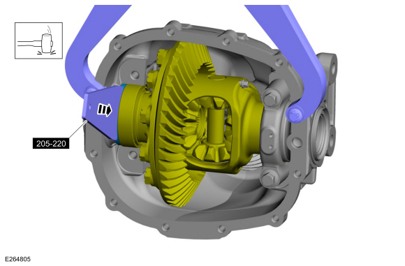
Using the special tool and a soft face copper mallet, install the LH selected ring gear back lash shim.
Use Special Service Tool: 205-220 Installer, Differential Shim.
Use the General Equipment: Copper Hammer
 |
-
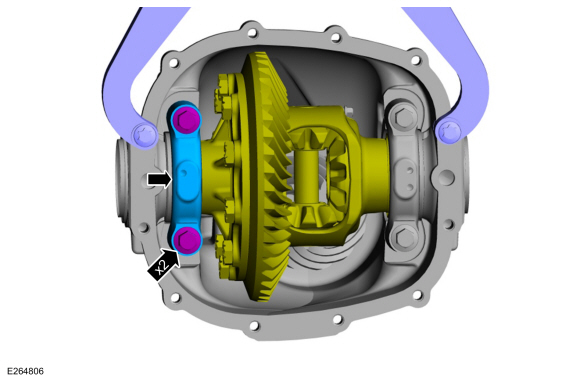
NOTE: The differential bearing cap bolts should only be finger tight at this time.
Install the LH differential bearing cap and the differential bearing cap bolts.
 |
-
Tighten the differential bearing cap bolts.
Torque: 83 lb.ft (112 Nm)
 |
-
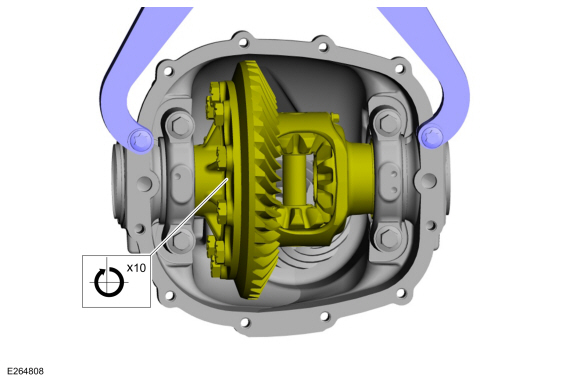
Rotate the differential several times, to assure the differential assembly rotates freely.
 |
-
Using the dial indicator gauge with holding fixture, do a final check of the ring gear backlash.
Use the General Equipment: Dial Indicator
|
- Apply marking compound and rotate the differential assembly 5 complete revolutions.
-
Verify an acceptable ring gear tooth pattern check.
Refer to: Rear Drive Axle and Differential (205-02 Rear Drive Axle/Differential - Ford 9.75 Inch Ring Gear) .
-
NOTE: This step requires the aid of another technician.
Remove the differential assembly from transmission holding fixture and position it on a workbench.
|
-
Install the differential housing cover.
Refer to: Differential Housing Cover (205-02 Rear Drive Axle/Differential - Vehicles With: Ford 9.75 Inch Ring Gear, Removal and Installation).
-
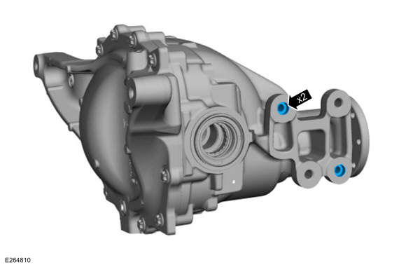
Install the new torque arm locating sleeves.
 |
-
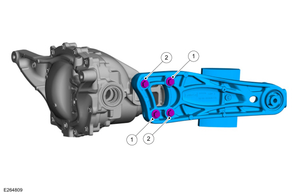
NOTE: The torque arm bolts must be tightened in the sequence below. If there is clearance in-between the head of the bolt and the torque arm, remove the torque arm bolts and reinstall following the sequence below.
Position the torque arm to the rear axle housing and install the new torque arm bolts hand tight.
Torque:
Tighten item 1 to : 20 lb.ft (27 Nm)
Tighten item 2 to : 150 lb.ft (203 Nm)
Tighten item 1 to : 150 lb.ft (203 Nm)
 |
-
NOTE: This step requires the aid of another technician.
Transfer the rear axle assembly from the workbench to the transmission jack.
 |
-
Install the rear axle assembly.
Refer to: Axle Assembly (205-02 Rear Drive Axle/Differential - Vehicles With: Ford 9.75 Inch Ring Gear, Removal and Installation).
 Differential Fluid Level Check. General Procedures
Materials
Name
Specification
Motorcraft® SAE 75W-85 Premium Synthetic Hypoid Gear LubricantXY-75W85-QL
WSS-M2C942-A
Check
With the vehicle in NEUTRAL, position it on a hoist...
 Ring Gear Backlash Adjustment - Vehicles With: Electronic Limited-Slip Differential. General Procedures
Special Tool(s) /
General Equipment
205-220Installer, Differential ShimTKIT-1985-FH
307-003
(T57L-500-B)
Holding Fixture, Transmission
Dial Indicator
Copper Hammer
Adjustment
Remove the rear axle assembly...
Other information:
Lincoln Navigator 2018-2026 Workshop Manual: Liftgate Window Latch. Removal and Installation
Removal Remove the liftgate trim panel. Refer to: Liftgate Trim Panel (501-05 Interior Trim and Ornamentation, Removal and Installation). Open the liftgate window glass. Remove the liftgate window latch...
Lincoln Navigator 2018-2026 Workshop Manual: Front Lower Control Arm Bracket. Removal and Installation
Special Tool(s) / General Equipment Grinder 8 mm Drill Bit MIG/MAG Welding Equipment Locking Pliers Removal Restore the vehicle to manufacturer's dimensions if required. Refer to: Body and Frame (501-26 Body Repairs - Vehicle Specific Information and Tolerance Checks, Description and Operation)...
Categories
- Manuals Home
- 4th Gen Lincoln Navigator Service Manual (2018 - 2026)
- Front Bumper Cover. Removal and Installation
- Neutral Flat Tow Activation and Deactivation. General Procedures
- Brake Service Mode Activation and Deactivation. General Procedures
- Identification Codes. Description and Operation
- All Terrain Control Module (ATCM). Removal and Installation
Rear Camber Adjustment. General Procedures
Special Tool(s) / General Equipment
Wheel Alignment SystemActivation
NOTICE: Suspension fasteners are critical parts that affect the performance of vital components and systems. Failure of these fasteners may result in major service expense. Use the same or equivalent parts if replacement is necessary. Do not use a replacement part of lesser quality or substitute design. Tighten fasteners as specified.
Using alignment equipment and the manufacturer's instructions, measure the rear camber.Use the General Equipment: Wheel Alignment System