Lincoln Navigator: Rear Suspension / Rear Stabilizer Bar. Removal and Installation
Removal
NOTICE: Suspension fasteners are critical parts that affect the performance of vital components and systems. Failure of these fasteners may result in major service expense. Use the same or equivalent parts if replacement is necessary. Do not use a replacement part of lesser quality or substitute design. Tighten fasteners as specified.
-
Remove the wheel and tire.
Refer to: Wheel and Tire (204-04A Wheels and Tires, Removal and Installation).
-
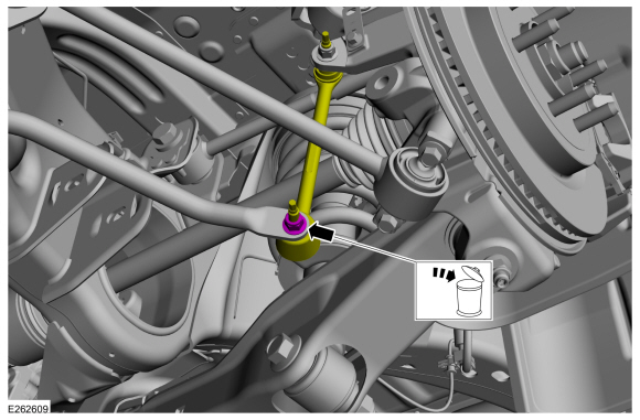
NOTICE: Do not use power tools to remove or install the stabilizer bar link nuts. Damage to the stabilizer bar link ball joints and boots may occur.
NOTE: Use the hex-holding feature to prevent the ball stud from turning while removing the stabilizer bar link nut.
On both sides.
Remove and discard the rear stabilizer bar link nut and keep aside stabilizer bar link.
 |
-
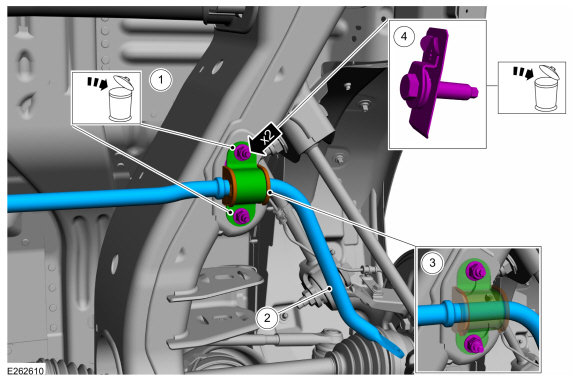
NOTE: Note the position of the components before removal.
On both sides.
-
Remove and discard the rear stabilizer bar bracket nuts.
-
Remove the rear stabilizer bar.
-
Remove the rear stabilizer bar bushings.
-
Remove and discard the rear stabilizer bar stud plates.
-
Remove and discard the rear stabilizer bar bracket nuts.
 |
Installation
-
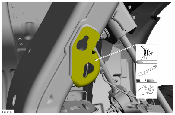
On both sides
Inspect and thoroughly clean both sides of the frame bracket mounting surfaces.
 |
-
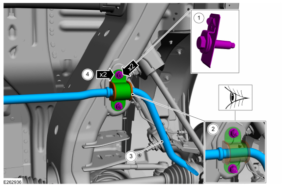
On both sides.
-
Insert the new stud plates into the frame bracket holes.
-
Inspect and if necessary, install new rear stabilizer bar bushings.
-
NOTE: Make sure that the component is correctly installed.
Install the rear stabilizer bar with the hump facing down towards the ground.
-
Install the new rear stabilizer bar bracket nuts.
Torque: 35 lb.ft (48 Nm)
-
Insert the new stud plates into the frame bracket holes.
 |
-
NOTICE: Do not use power tools to remove or install the stabilizer bar link nuts. Damage to the stabilizer bar link ball joints and boots may occur.
NOTE: The stabilizer bar links are designed with low friction ball joints that have a low breakaway torque.
On both sides.
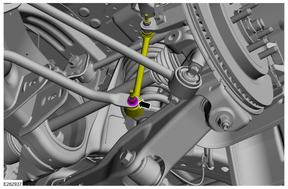
Position the rear stabilizer bar link and install the new rear stabilizer bar link nut.
Torque: 46 lb.ft (63 Nm)
 |
-
Install the wheel and tire.
Refer to: Wheel and Tire (204-04A Wheels and Tires, Removal and Installation).
 Lower Trailing Arm. Removal and Installation
Removal
NOTICE:
Suspension fasteners are critical parts that affect the
performance of vital components and systems. Failure of these fasteners
may result in major service expense...
 Rear Stabilizer Bar Link. Removal and Installation
Removal
NOTE:
Removal steps in this procedure may contain installation details.
With the vehicle in NEUTRAL, position it on a hoist...
Other information:
Lincoln Navigator 2018-2026 Workshop Manual: Special Testing Procedures. Diagnosis and Testing
Line Pressure Test This test verifies the line pressure is within specification. If available, refer to the Transmission Line Pressure Test general procedure to access the line pressure tap. If equipped, remove the heat shield...
Lincoln Navigator 2018-2026 Workshop Manual: Direct Injection Fuel Rail LH. Removal and Installation
Special Tool(s) / General Equipment 303-1567Sizer, Teflon SealTKIT-2010C-FLM 307-005 (T59L-100-B) Slide Hammer 310-205Fuel Injector Brush 310-206Remover, Fuel InjectorTKIT-2009A-FLM 310-207Installer, Fuel Injector Seal AssemblyTKIT-2009A-FLM Removal Remove the direct injection fuel rail RH...
Categories
- Manuals Home
- 4th Gen Lincoln Navigator Service Manual (2018 - 2026)
- Transmission Fluid Drain and Refill. General Procedures
- Telematics Control Unit (TCU) Module. Removal and Installation
- Windshield Washer Pump. Removal and Installation
- Neutral Flat Tow Activation and Deactivation. General Procedures
- Remote Function Actuator (RFA) Module. Removal and Installation
Wheel to Hub Runout Minimization. General Procedures
Check
NOTE: Wheel-to-hub optimization is important. Clearance between the wheel and hub can be used to offset or neutralize the Road Force® or run-out of the wheel and tire assembly. For every 0.001 inch of wheel-to-hub clearance, the Road Force® can be affected between 1 and 3 pounds depending on the tire stiffness.
NOTE: The example below illustrates how the clearance between the wheel and the hub can be used to offset the high spot of radial run-out or Road Force®. Following the procedure will make sure of the best optimization.
Position the wheel and tire assembly on the vehicle so that the high spot location of radial run-out or Road Force® is at the 6 o'clock position and