Lincoln Navigator: Generator and Regulator / Generator. Removal and Installation
Removal
NOTE: Removal steps in this procedure may contain installation details.
-
With the vehicle in NEUTRAL, position it on a hoist.
Refer to: Jacking and Lifting (100-02 Jacking and Lifting, Description and Operation).
-
Disconnect the battery.
Refer to: Battery Disconnect and Connect (414-01 Battery, Mounting and Cables, General Procedures).
-
NOTICE: The turbocharger compressor vanes can be damaged by even the smallest particles. When removing any turbocharger or engine air intake system component, ensure that no debris enters the system. Failure to do so may result in damage to the turbocharger.
Remove the left side CAC intake pipe.
Refer to: Charge Air Cooler (CAC) Intake Pipe (303-12 Intake Air Distribution and Filtering - 3.5L EcoBoost (272kW/370PS), Removal and Installation).
-
Remove the LH air cleaner outlet pipe.
Refer to: Air Cleaner Outlet Pipe LH (303-12 Intake Air Distribution and Filtering - 3.5L EcoBoost (272kW/370PS), Removal and Installation).
-
-
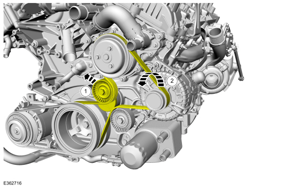
Rotate the accessory drive belt tensioner counterclockwise.
-
Position the accessory drive belt aside.
-
Rotate the accessory drive belt tensioner counterclockwise.
 |
-
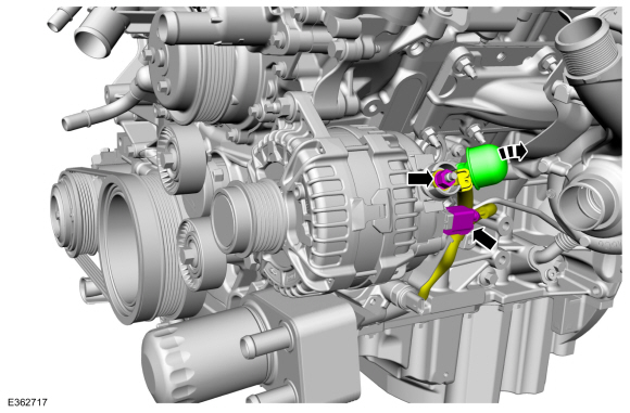
NOTICE: When installing the B+ terminal nut to the generator, finger-start the nut before tightening or component damage may occur.
Disconnect the generator electrical connector. Position the B+ wire protective cover, remove the nut and position the B+ wire aside.
Torque: 150 lb.in (17 Nm)
 |
-
-
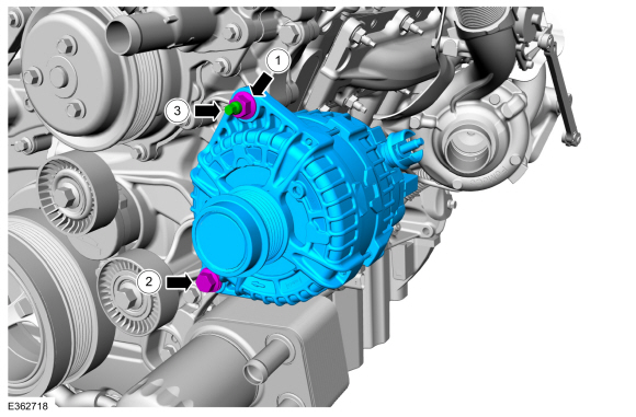
Remove the generator stud nut.
Torque: 35 lb.ft (47 Nm)
-
Remove the generator bolt.
Torque: 35 lb.ft (47 Nm)
-
Remove the generator stud bolt and the generator.
Torque: 71 lb.in (8 Nm)
-
Remove the generator stud nut.
 |
Installation
-
To install, reverse the removal procedure.
 Specifications
General Specifications
Item
Specification
Rating
260 amps
Generator amps at
80...
 Generator Pulley. Removal and Installation
Removal
WARNING:
Before beginning any service procedure in this
section, refer to Safety Warnings in section 100-00 General Information...
Other information:
Lincoln Navigator 2018-2026 Workshop Manual: Air Inlet Door Actuator. Removal and Installation
Removal NOTE: Removal steps in this procedure may contain installation details. Remove the instrument panel. Refer to: Instrument Panel (501-12 Instrument Panel and Console, Removal and Installation). Disconnect the electrical connector, remove the retainers and the air inlet door actuator...
Lincoln Navigator 2018-2026 Workshop Manual: Rear Toe Adjustment. General Procedures
Special Tool(s) / General Equipment Wheel Alignment System Activation NOTICE: Do not use any tools or equipment to move the wheel and tire assembly or suspension components while checking for relative movement. Suspension damage may occur...
Categories
- Manuals Home
- 4th Gen Lincoln Navigator Service Manual (2018 - 2026)
- Rear View Mirrors - System Operation and Component Description. Description and Operation
- All Terrain Control Module (ATCM). Removal and Installation
- Identification Codes. Description and Operation
- Rear Bumper. Removal and Installation
- Power Running Board (PRB). Diagnosis and Testing
Front Stabilizer Bar Link. Removal and Installation
Removal
NOTICE: Suspension fasteners are critical parts that affect the performance of vital components and systems. Failure of these fasteners may result in major service expense. Use the same or equivalent parts if replacement is necessary. Do not use a replacement part of lesser quality or substitute design. Tighten fasteners as specified.
NOTE: Removal steps in this procedure may contain installation details.
With the vehicle in NEUTRAL, position it on a hoist.Refer to: Jacking and Lifting (100-02 Jacking and Lifting, Description and Operation).
NOTICE: Do not use power tools to remove or install the stabilizer bar