Lincoln Navigator: Engine - 3.5L EcoBoost (272kW/370PS) / Engine Mount RH. Removal and Installation
Special Tool(s) /
General Equipment
 |
303-1246
Engine Spreader Bar
TKIT-2006UF-FLM
TKIT-2006UF-ROW |
 |
303-1654
Lift Eyes |
 |
303-F070
Support Bar, Engine
TKIT-1999A-F/LT
TKIT-1999A-FM/FLM |
Materials
| Name |
Specification |
Motorcraft® Threadlock 262
TA-26 |
WSK-M2G351-A6
|
Removal
NOTE:
Discard all engine mount fasteners and install new fasteners.
-
With the vehicle in NEUTRAL, position it on a hoist.
Refer to: Jacking and Lifting (100-02 Jacking and Lifting, Description and Operation).
-
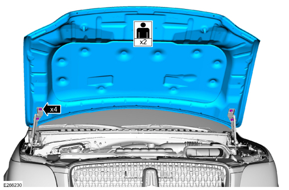
On both sides.
Index-mark the hood hinge location.
-
Remove the nuts and the hood.
-
-
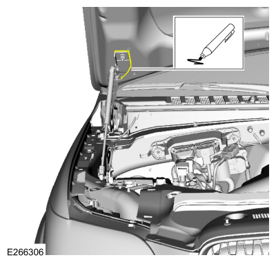
Release the clip.
-
Detach and position the hood shock aside.
-
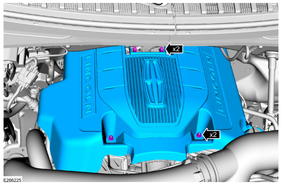
If equipped.
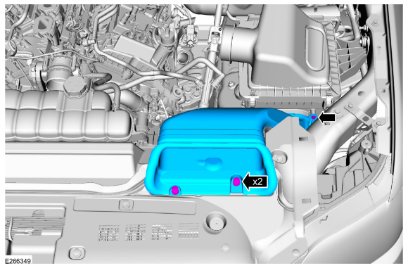
Remove the engine appearance cover retainers, release
the engine appearance cover from the rear retainers and then remove the
engine appearance cover.
-
Remove CAC intake pipe.
Refer to: Charge Air Cooler (CAC) Intake Pipe (303-12 Intake Air
Distribution and Filtering - 3.5L EcoBoost (272kW/370PS), Removal and
Installation).
-
Remove CAC outlet pipe.
Refer to: Air Cleaner Outlet Pipe RH (303-12 Intake Air Distribution
and Filtering - 3.5L EcoBoost (272kW/370PS), Removal and Installation).
-
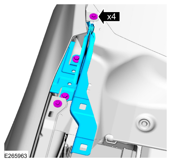
Remove the nuts and position aside the CAC tube bracket.
-
Remove the intake manifold.
Refer to: Intake Manifold (303-01 Engine - 3.5L EcoBoost (272kW/370PS), Removal and Installation).
-
Remove the right rear ignition coil.
Refer to: Ignition Coil-On-Plug (303-07 Engine Ignition - 3.5L EcoBoost (272kW/370PS), Removal and Installation).
-
Remove the cowl panel.
Refer to: Cowl Panel (501-02 Front End Body Panels, Removal and Installation).
-
Remove the bolt and pin-type retainers and the air cleaner inlet tube.
-
Remove the pin-type retainers and the air deflector.
-
On both sides.
Index-mark the hood hinge location.
-
On both sides.
Remove the bolts and the hood hinge.
-
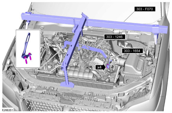
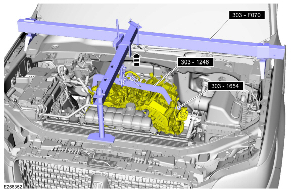
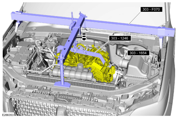
Install the special tools.
Install Special Service Tool: 303-F070
Support Bar, Engine.
, 303-1246
Engine Spreader Bar.
, 303-1654
Lift Eyes.
Torque:
18 lb.ft (25 Nm)
-
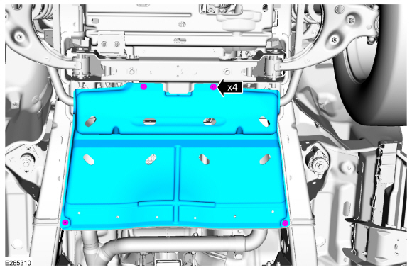
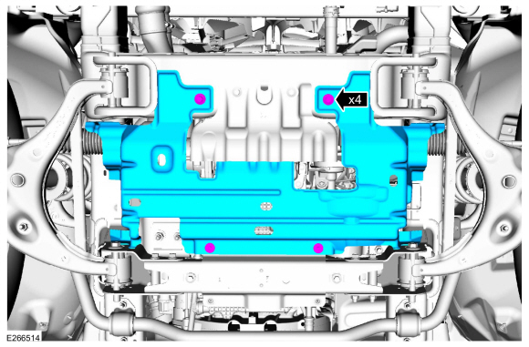
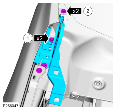
Remove the bolts and the transmission housing cover.
-
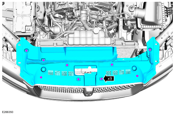
Remove the bolts and the underbody shield.
-
If equipped, remove the front driveshaft.
Refer to: Front Driveshaft (205-01 Driveshaft, Removal and Installation).
-
NOTE:
Make sure that the mating faces are clean and free of foreign material.
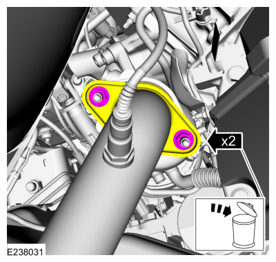
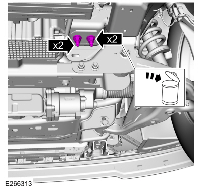
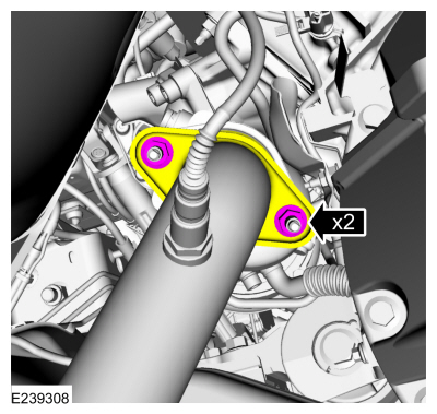
Remove and discard the LH catalytic converter flange nuts.
-
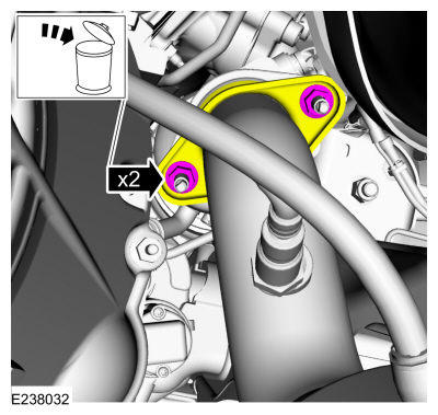
NOTE:
Make sure that the mating faces are clean and free of foreign material.
Remove and discard the RH catalytic converter flange nuts.
-
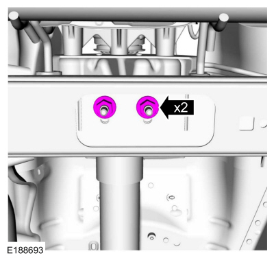
NOTICE:
Only use hand tools when removing the transmission
mount-to-crossmember nuts or damage to the transmission mount can occur.
Loosen the transmission mount-to-crossmember nuts.
-
Remove the following items:
-
Remove the starter motor.
Refer to: Starter Motor (303-06 Starting System - 3.5L EcoBoost (272kW/370PS), Removal and Installation).
-
Remove the A/C belt.
Refer to: Air Conditioning (A/C) Compressor Belt (303-05 Accessory
Drive - 3.5L EcoBoost (272kW/370PS), Removal and Installation).
-
Disconnect the coolant pump electrical connector. Remove the bolts and position aside the coolant pump.
-
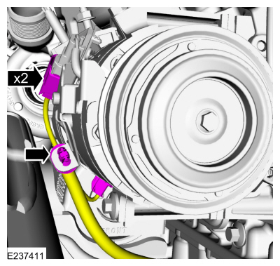
Disconnect the A/C compressor electrical connectors and wire retainer.
-
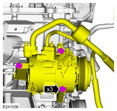
Remove the bolts and position aside the A/C compressor.
-
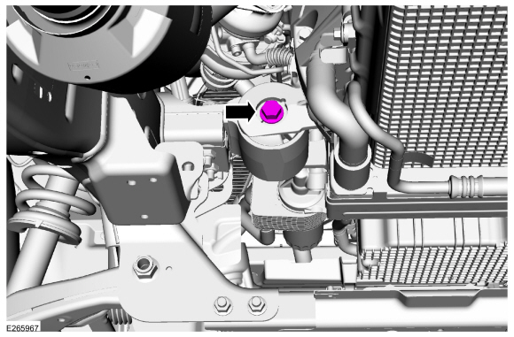
NOTICE:
Only use hand tools when loosening or tightening the
engine mount through bolts or damage to the engine mount-to-cylinder
block bracket can occur.
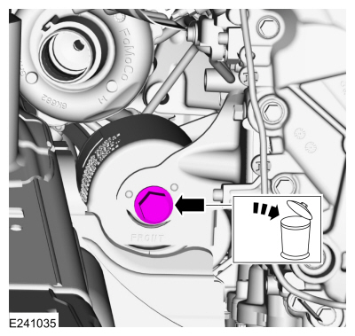
Remove and discard the RH engine mount through bolt.
-
NOTICE:
Only use hand tools when loosening or tightening the
engine mount through bolts or damage to the engine mount-to-cylinder
block bracket can occur.
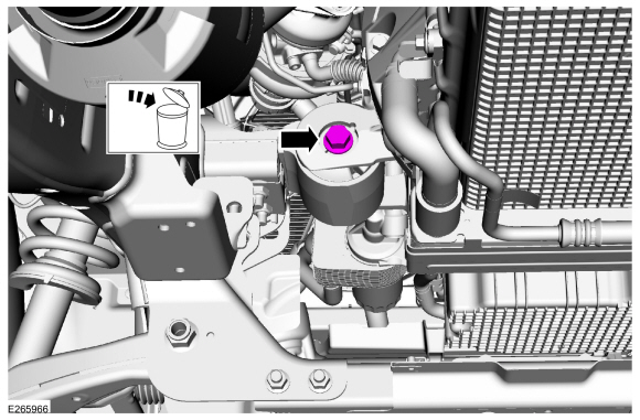
Remove and discard the LH engine mount through bolt.
-
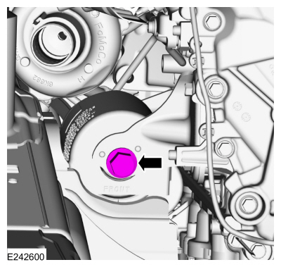
NOTICE:
Only use hand tools when loosening or tightening the
engine mount nuts and studs or damage to the engine mount can occur.
NOTE:
The engine mount studs may come off with the nuts.
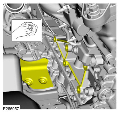
Remove and discard the engine mount nuts. Remove the engine mount studs.
-
Raise the engine approximately 30 mm (1.18 in).
-
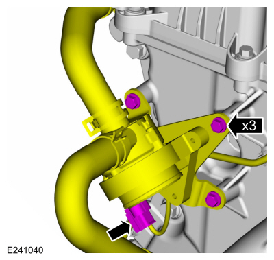
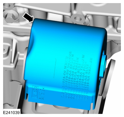
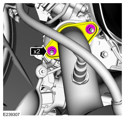
Remove the bolts and the RH engine mount-to-cylinder block bracket. Discard the bolts.
-
Remove the RH engine mount.
Installation
-
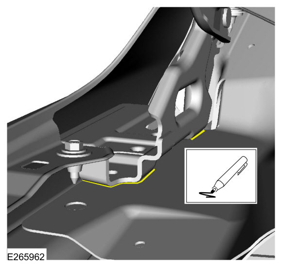
Clean the engine mount-to-cylinder block and engine
mount-to-frame mating surfaces of any dirt or foreign material prior to
installation.
-
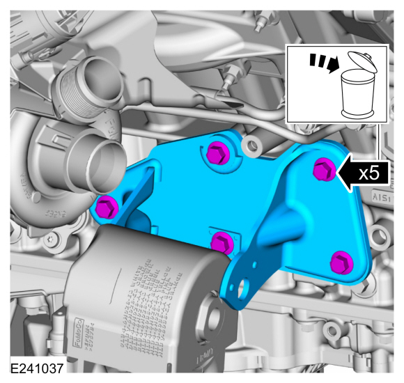
Position the RH engine mount into the vehicle.
-
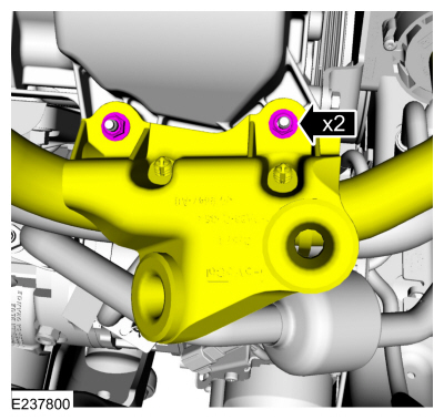
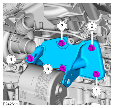
Position the RH engine mount-to-cylinder block bracket and install the new bolts in the sequence shown.
Torque:
57 lb.ft (77 Nm)
-
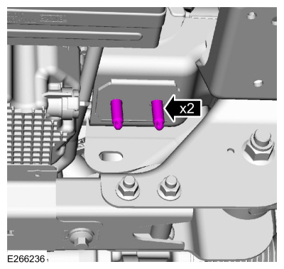
NOTICE:
Only use hand tools when installing the engine mount studs or damage to the engine mount can occur.
NOTE:
Apply threadlock to the stud threads prior to installation.
Install the RH engine mount studs.
Material: Motorcraft® Threadlock 262
/ TA-26
(WSK-M2G351-A6)
Torque:
22 lb.ft (30 Nm)
-
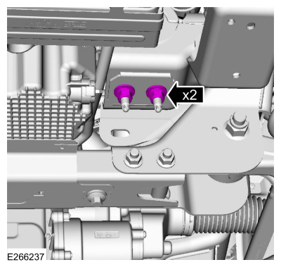
NOTICE:
Only use hand tools when installing the RH engine mount nuts or damage to the engine mount can occur.
Install the new RH engine mount nuts.
Torque:
111 lb.ft (150 Nm)
-
Lower the engine to the installed position.
-
NOTICE:
Only use hand tools when loosening or tightening the
engine mount through bolts or damage to the engine mount-to-cylinder
block bracket can occur.
Install the new LH engine mount through bolt.
Torque:
258 lb.ft (350 Nm)
-
NOTICE:
Only use hand tools when loosening or tightening the
engine mount through bolts or damage to the engine mount-to-cylinder
block bracket can occur.
Install the new RH engine mount through bolt.
Torque:
258 lb.ft (350 Nm)
-
Position back the A/C compressor and install the bolts.
Torque:
18 lb.ft (25 Nm)
-
Connect the A/C compressor electrical connectors and wire retainer.
-
Position back the coolant pump and install the bolts. Connect the coolant pump electrical connector.
Torque:
62 lb.in (7 Nm)
-
Install the following items:
-
Install the A/C compressor belt.
Refer to: Air Conditioning (A/C) Compressor Belt (303-05 Accessory
Drive - 3.5L EcoBoost (272kW/370PS), Removal and Installation).
-
Install the starter motor.
Refer to: Starter Motor (303-06 Starting System - 3.5L EcoBoost (272kW/370PS), Removal and Installation).
-
NOTICE:
Only use hand tools when loosening or tightening the
transmission mount-to-crossmember nuts or damage to the transmission
mount can occur.
Remove and discard the transmission mount-to-crossmember
nuts. Install new transmission mount-to-crossmember nuts.
Torque:
85 lb.ft (115 Nm)
-
Install the new RH catalytic converter-to-turbocharger nuts.
Torque:
30 lb.ft (40 Nm)
-
Install the new LH catalytic converter-to-turbocharger nuts.
Torque:
30 lb.ft (40 Nm)
-
If equipped.
Install the front driveshaft.
Refer to: Front Driveshaft (205-01 Driveshaft, Removal and Installation).
-
-
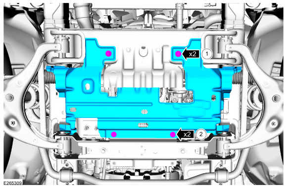
Install the underbody shield and the bolts.
Torque:
30 lb.ft (40 Nm)
-
Install the underbody shield and the bolts
Torque:
71 lb.in (8 Nm)
-
-
Install the transmission housing cover and attach the bolts.
Torque:
71 lb.in (8 Nm)
-
Remove the special tools.
Remove Special Service Tool: 303-F070
Support Bar, Engine.
, 303-1246
Engine Spreader Bar.
, 303-1654
Lift Eyes.
-
Install the air deflector and pin-type retainers.
-
Install the air cleaner inlet tube, pin-type retainers and bolt.
-
NOTE:
Align the index marks made during hinge removal.
On Both sides.
-
Install the hood hinge and bolts.
Torque:
22 lb.ft (30 Nm)
-
Install the fender to hood hinge bolts.
Torque:
80 lb.in (9 Nm)
-
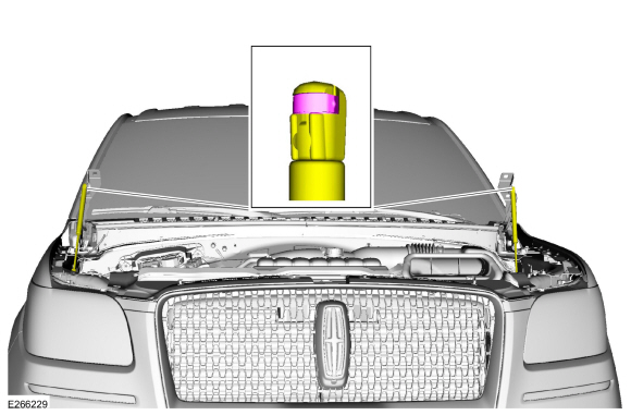
Install the struts.
-
NOTE:
Align the index marks made during hood removal.
Position the hood and install the nuts.
Torque:
18 lb.ft (25 Nm)
-
Install the right rear ignition coil.
Refer to: Ignition Coil-On-Plug (303-07 Engine Ignition - 3.5L EcoBoost (272kW/370PS), Removal and Installation).
-
Install the intake manifold.
Refer to: Intake Manifold (303-01 Engine - 3.5L EcoBoost (272kW/370PS), Removal and Installation).
-
Position back the CAC tube bracket and install the nuts.
Torque:
53 lb.in (6 Nm)
-
Install the CAC outlet pipe.
Refer to: Charge Air Cooler (CAC) Outlet Pipe (303-12 Intake Air
Distribution and Filtering - 3.5L EcoBoost (272kW/370PS), Removal and
Installation).
-
Install the CAC intake pipe.
Refer to: Charge Air Cooler (CAC) Intake Pipe (303-12 Intake Air
Distribution and Filtering - 3.5L EcoBoost (272kW/370PS), Removal and
Installation).
-
Install the cowl panel.
Refer to: Cowl Panel (501-02 Front End Body Panels, Removal and Installation).
-
Slide the engine appearance cover into the retaining bracket and install the retainers.
Torque:
97 lb.in (11 Nm)
-
Start and check the exhaust system for leaks.
Special Tool(s) /
General Equipment
303-1246Engine Spreader BarTKIT-2006UF-FLMTKIT-2006UF-ROW
303-1654Lift Eyes
303-F070Support Bar, EngineTKIT-1999A-F/LTTKIT-1999A-FM/FLM
Vehicle/Axle Stands
Removal
NOTICE:
Use care when positioning the front axle housing or the
vacuum lines to the axle solenoid may become disconnected or damaged...
Materials
Name
Specification
Motorcraft® Metal Surface Prep WipesZC-31-B
-
Removal
With the vehicle in NEUTRAL, position it on a hoist...
Other information:
Overview
Power Headrest Fold
The power headrest fold control switch is located in the overhead console. When the switch is activated, the LH and RH
headrests fold forward to allow clear vision for the driver and/or to
allow the seat to be folded foward to the stowed position...
Special Tool(s) /
General Equipment
Interior Trim Remover
Adjustment
Vertical Alignment
NOTE:
In order to align the CCM
, the front bumper trim panel must be removed to access the sensor and
the vehicle must be in a wheel alignment bay station so that the vehicle
is level...
 Engine Mount LH. Removal and Installation
 Exhaust Manifold LH. Removal and Installation