Lincoln Navigator: Rear Drive Axle/Differential - Vehicles With: Ford 9.75 Inch Ring Gear / Differential Carrier - Vehicles With: Electronic Limited-Slip Differential. Disassembly and Assembly
Special Tool(s) / General Equipment
| Punch | |
| Copper Hammer |
DISASSEMBLY
NOTE: The eLSD hydraulic actuator LH RH case, clutch pack assembly, and HCU are only available with the differential carrier assembly.
-
Remove the hydraulic actuator assembly from the differential case.
Refer to: Hydraulic Actuator (205-02 Rear Drive Axle/Differential - Vehicles With: Ford 9.75 Inch Ring Gear, Removal and Installation).
-
Remove and discard the ring gear bolts.
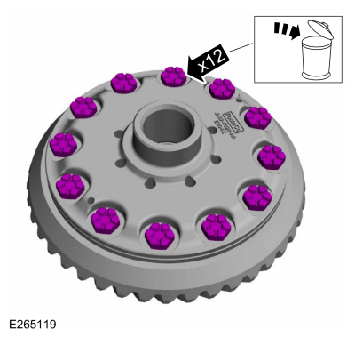 |
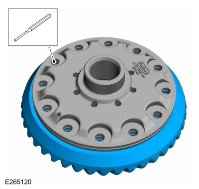
-
NOTICE: Care should be taken not to damage the differential ring gear bolt hole threads.
Using the general equipment, remove the ring gear.
Use the General Equipment: Punch
Use the General Equipment: Copper Hammer
 |
-
NOTICE: The differential flange and ring gear flange must be free of any old retaining compound material. Make sure both surfaces are clean and free of oil, dust and debris. Failure to clean the surfaces can result in ring gear runout concerns.
NOTE: Use solvent and Scotch-Brite® pads to remove.
Clean all traces of the old retaining compound material from the differential flange.
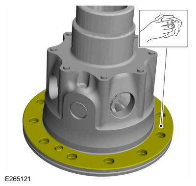 |
ASSEMBLY
-
NOTE: Make sure that a new component is installed.
NOTE: Tighten the ring gear bolts in a cross pattern.
Install the ring gear and the new differential ring gear bolts.
Torque: 140 lb.ft (190 Nm)
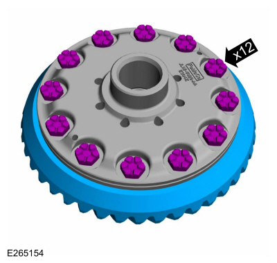 |
-
Install the hydraulic actuator assembly to the differential case.
Refer to: Hydraulic Actuator (205-02 Rear Drive Axle/Differential - Vehicles With: Ford 9.75 Inch Ring Gear, Removal and Installation).
 Rear Halfshaft Seal. Removal and Installation
Special Tool(s) /
General Equipment
205-907Handle, 32 DriverTKIT-2008DH-FLM
206-034
(T88P-20202-B)
Installer, Wheel Speed Sensor RingTKIT-1988-FLMTKIT-1988-LM
Feeler Gauge
Removal
NOTE:
Removal steps in this procedure may contain installation details...

Other information:
Lincoln Navigator 2018-2026 Workshop Manual: A-Pillar Outer Panel. Removal and Installation
Special Tool(s) / General Equipment 6.5 mm Drill Bit Spherical Cutter Polydrive Bit Socket Self-Piercing Rivet (SPR) Remover/Installer Belt Sander Blind Rivet Gun Hot Air Gun Air Body Saw MIG/MAG Welding Equipment Locking Pliers Materials Name Specification Metal Bonding AdhesiveTA-1, TA-1-B, 3M..
Lincoln Navigator 2018-2026 Workshop Manual: Valve Cover LH. Removal and Installation
Special Tool(s) / General Equipment 205-142 (T80T-4000-J) Installer, Differential Bearing Cone 205-153 (T80T-4000-W) Handle 303-1247VCT Spark Plug Tube Seal Remover and InstallerTKIT-2006UF-FLMTKIT-2006UF-ROW Materials Name Specification Motorcraft® High Performance Engine RTV SiliconeTA-357 WSE-M4G323-A6 Motorcra..
Categories
- Manuals Home
- 4th Gen Lincoln Navigator Service Manual (2018 - 2026)
- Rear View Mirrors - System Operation and Component Description. Description and Operation
- Identification Codes. Description and Operation
- Body Control Module (BCM). Removal and Installation
- Transmission Fluid Drain and Refill. General Procedures
- Vehicle Dynamics Control Module (VDM). Removal and Installation
Axle Tube Bearing. Removal and Installation
Special Tool(s) / General Equipment
 205-123
(T78P-1177-A)
205-123
(T78P-1177-A)
Installer, Axle Shaft Oil Seal
 308-047
(T77F-1102-A)
308-047
(T77F-1102-A)
Remover, Bearing Cup Slide Hammer