Lincoln Navigator: Charging System - General Information / Charging System - 3.5L EcoBoost (272kW/370PS) - Overview. Description and Operation
Overview
The generator is driven by the FEAD belt. When the engine is started, the generator begins to generate AC voltage which is internally converted to DC voltage. The DC voltage level is controlled by the voltage regulator (located on the rear of the generator) and is supplied to the battery.
The PCM controls the voltage regulation setpoint and communicates this information to the generator internal voltage regulator over a LIN communication circuit.
This vehicle is equipped with an Electrical energy management system (load shed strategy). The BCM monitors the battery state of charge using information from the battery monitoring sensor attached to the negative battery post and manages battery charging.
The PCM monitors the generator current using over LIN .
 Charging System - 3.5L EcoBoost (272kW/370PS) - System Operation and Component Description. Description and Operation
System Operation
System Diagram
E344411
*.sttxt {
visibility: hidden;
}
*.stcallout {
visibility: visible;
}
1
PCM
2
Generator
3
BCM
4
GWM
5
IPC
6
BMS
..
Other information:
Lincoln Navigator 2018-2026 Workshop Manual: Rear Audio Control Module (RACM). Removal and Installation
Special Tool(s) / General Equipment Interior Trim Remover Removal NOTE: If installing a new module, it is necessary to upload the module configuration information to the scan tool prior to removing the module. This information must be downloaded into the new module after installation. Using a diagnostic scan tool, begin the PMI process for the RACM follo..
Lincoln Navigator 2018-2026 Workshop Manual: Main Control Valve Body. Description and Operation
Item Description 1 Internal wiring harness retaining bolt 2 Internal wiring harness 3 Park lock pawl solenoid 4 Solenoid retaining plate bolts 5 Solenoid retaining plate 6 TCC solenoid ..
Categories
- Manuals Home
- 4th Gen Lincoln Navigator Service Manual (2018 - 2026)
- Power Running Board (PRB). Diagnosis and Testing
- Telematics Control Unit (TCU) Module. Removal and Installation
- Brake Service Mode Activation and Deactivation. General Procedures
- All Terrain Control Module (ATCM). Removal and Installation
- Rear Bumper. Removal and Installation
Rear Stabilizer Bar Link. Removal and Installation
Removal
NOTE: Removal steps in this procedure may contain installation details.
With the vehicle in NEUTRAL, position it on a hoist.Refer to: Jacking and Lifting (100-02 Jacking and Lifting, Description and Operation).
NOTE: Use the hex-holding feature to prevent the stud from turning while removing the nut.
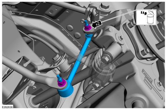
Remove and discard the 2 rear stabilizer bar link nuts and remove the rear stabilizer bar link.Torque: 46 lb.ft (63 Nm)


