Lincoln Navigator: Side and Rear Vision / Side Obstacle Detection Control Module (SODCM). Removal and Installation
Removal
Side obstacle detection control module
-
NOTE: This step is only necessary if the SODL or SODR is being replaced.
Using a diagnostic scan tool, begin the PMI process for the SODL or SODR following the on-screen instructions.
-
Remove the rear bumper cover.
Refer to: Rear Bumper Cover (501-19 Bumpers, Removal and Installation).
-
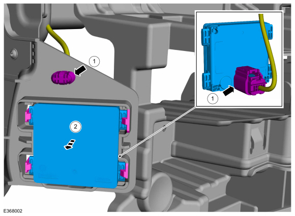
Remove the SODL or SODR .
-
Disconnect the SODL or SODR electrical connector and retainer.
-
Release the tabs and remove the SODL or SODR .
-
Disconnect the SODL or SODR electrical connector and retainer.
 |
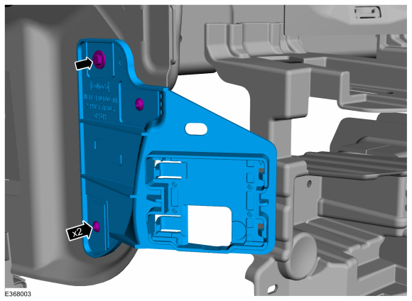
Side obstacle detection control module bracket
-
Remove the SODL or SODR .
-
Remove the screws and the SODL or SODR bracket.
Torque: 13 lb.in (1.5 Nm)
 |
Installation
-
To install, reverse the removal procedure.
-
NOTE: Carry out this step only if a SODL or SODR is being replaced.
Using a diagnostic scan tool, complete the PMI process for the SODL or SODR following the on-screen instructions.
 Blind Spot Information System. Diagnosis and Testing
Diagnostic Trouble Code (DTC) Chart
Diagnostics in this manual assume a certain skill level and knowledge of Ford-specific diagnostic practices. REFER to: Diagnostic Methods (100-00 General Information, Description and Operation)...
 Side Obstacle Detection Control Module C (SODCMC). Removal and Installation
Removal
NOTE:
Removal steps in this procedure may contain installation details.
Remove the front bumper cover.
Refer to: Front Bumper Cover (501-19 Bumpers, Removal and Installation)...
Other information:
Lincoln Navigator 2018-2026 Workshop Manual: Front Seat Power Lumbar Assembly - Vehicles With: Multi-Contour Seats. Removal and Installation
Special Tool(s) / General Equipment Interior Trim Remover Removal NOTE: Driver seat shown, passenger seat similar. NOTE: The front seat backrest driver seat SCMG (driver multi-contour seat module)/SCMH (passenger multi-contour seat module) is part of the front seat power lumbar assembly and is serviced as an assembly...
Lincoln Navigator 2018-2026 Workshop Manual: Rear Toe Adjustment. General Procedures
Special Tool(s) / General Equipment Wheel Alignment System Activation NOTICE: Do not use any tools or equipment to move the wheel and tire assembly or suspension components while checking for relative movement. Suspension damage may occur...
Categories
- Manuals Home
- 4th Gen Lincoln Navigator Service Manual (2018 - 2026)
- Head Up Display (HUD) Module Calibration. General Procedures
- All Terrain Control Module (ATCM). Removal and Installation
- Front Bumper Cover. Removal and Installation
- Neutral Flat Tow Activation and Deactivation. General Procedures
- Transmission Fluid Drain and Refill. General Procedures
Wheel to Hub Runout Minimization. General Procedures
Check
NOTE: Wheel-to-hub optimization is important. Clearance between the wheel and hub can be used to offset or neutralize the Road Force® or run-out of the wheel and tire assembly. For every 0.001 inch of wheel-to-hub clearance, the Road Force® can be affected between 1 and 3 pounds depending on the tire stiffness.
NOTE: The example below illustrates how the clearance between the wheel and the hub can be used to offset the high spot of radial run-out or Road Force®. Following the procedure will make sure of the best optimization.
Position the wheel and tire assembly on the vehicle so that the high spot location of radial run-out or Road Force® is at the 6 o'clock position and