Lincoln Navigator: Perimeter Anti-Theft Alarm / Perimeter Anti-Theft Alarm - System Operation and Component Description. Description and Operation
System Operation
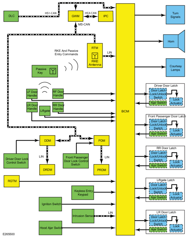
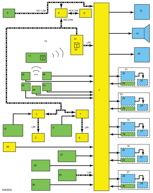
System Diagram
| Item | Description |
|---|---|
| 1 | BCM |
| 2 | DDM |
| 3 | DRDM |
| 4 | GWM |
| 5 | DLC |
| 6 | IPC |
| 7 | PDM |
| 8 | PRDM |
| 9 | Front Passenger Door Lock Control Switch |
| 10 | RKE Antenna |
| 11 | Passive Key |
| 12 | RKE And Passive Entry Commands |
| 13 | Turn Signals |
| 14 | Horn |
| 15 | RHR Door Latch |
| 16 | Door Latch Lock/Unlock Switch |
| 17 | Lock Actuator |
| 18 | Ajar Switch |
| 19 | Liftgate Latch |
| 20 | Door Latch Lock/Unlock Switch |
| 21 | Lock Actuator |
| 22 | Ajar Switch |
| 23 | Front Passenger Door Latch |
| 24 | Door Latch Lock/Unlock Switch |
| 25 | Lock Actuator |
| 26 | Ajar Switch |
| 27 | LHR Door Latch |
| 28 | Door Latch Lock/Unlock Switch |
| 29 | Lock Actuator |
| 30 | Ajar Switch |
| 31 | Driver Door Latch |
| 32 | Door Latch Lock/Unlock Switch |
| 33 | Lock Actuator |
| 34 | Ajar Switch |
| 35 | Ignition Switch |
| 36 | Hood Ajar Switch |
| 37 | Driver Door Lock Control Switch |
| 38 | Courtesy Lamps |
| 39 | Intrusion Sensor |
| 40 | RGTM |
| 41 | RTM |
| 42 | LHR Door Handle |
| 43 | RHR Door Handle |
| 44 | Liftgate |
| 45 | LHF Door Handle |
| 46 | RHF Door Handle |
| 47 | Keyless Entry Keypad |
Network Message Chart
Module Network Input Messages - BCM
| Broadcast Message | Originating Module | Message Purpose |
|---|---|---|
| Door lock switch status | DDM | Used by the BCM to arm the perimeter alarm. |
| Door lock switch status | PDM | Used by the BCM to arm the perimeter alarm. |
| RKE data | RTM | Used by the BCM to arm/disarm the perimeter alarm or to activate/deactivate the panic alarm. |
Module Network Input Messages - IPC
| Broadcast Message | Originating Module | Message Purpose |
|---|---|---|
| Perimeter alarm chime request | BCM | Used by the IPC to sound the perimeter alarm chime during the 12 second delay. |
CAN Protection Strategy
When the perimeter alarm is armed, the BCM monitors the CAN . If a scan tool is connected to the DLC , and an attempt is made to establish a session with the BCM , it activates the perimeter alarm.
Every time the BCM detects an unauthorized access (alarm activates), all BCM programming, PID
monitoring and self-test sessions are blocked for 10 minutes. At the
end of the 10 minute time period, the traffic horn chirps to indicate
the 1 minute of opportunity to communicate with the BCM and program keys if none are available.
Refer to: Anti-Theft Key Programming - Scan Tool (419-01B Passive Anti-Theft System (PATS), General Procedures).
Perimeter Alarm
The BCM controls the operation of the perimeter alarm. It monitors inputs from the RKE system, the passive entry system (if equipped), the power door lock system, the PATS and the ignition status to determine when to arm the perimeter alarm.
The BCM monitors all of the door ajar switches, the hood ajar switch, the CAN and the ignition status to determine when to activate the perimeter alarm. When the BCM detects an input indicating an unauthorized entry into the vehicle, the BCM activates the perimeter alarm by sounding the horn and flashing all the turn signals and interior courtesy lamps at regular intervals.
The BCM monitors the RKE system, the passive entry system, and the PATS to determine when to disarm the perimeter alarm.
A door lock LED
indicator located on each door window sill provides lock/unlock
indication for the corresponding door. They illuminate when the door is
locked and are off when the door is unlocked. For detailed information
of the door lock LED indicators,
Refer to: Handles, Locks, Latches
and Entry Systems - System Operation and Component Description (501-14
Handles, Locks, Latches and Entry Systems, Description and Operation).
Perimeter Alarm Arming
The perimeter alarm is ready to arm any time the ignition is off. The perimeter alarm pre-arms when any of the following actions are performed:
- Locking a front door or the liftgate using the passive entry feature
- Pressing the door lock control switch to the lock position with a front door open, and then closing the door
- Pressing the lock button on a programmed RKE transmitter
- Touching the 7/8 and 9/0 buttons simultaneously on the keyless entry keypad
Once the system is pre-armed, there is a 20 second countdown before the perimeter alarm is armed. Each entry point to the vehicle (hood, door, liftgate) is armed separately and must be closed before that entry point begins the 20 second countdown to become armed. If all entry points are closed, the turn signals flash upon locking indicating that all entry points are entering the 20 second countdown.
Perimeter Alarm Activation
The perimeter alarm has a 12 second delay when the driver front door is opened without using a RKE transmitter, the keyless entry keypad, or a passive key to unlock the vehicle. During the delay, a chime sounds. If the perimeter alarm is not disarmed within the 12 second delay, the alarm activates.
The perimeter alarm activates when any of the following actions are performed:
- The driver front door is opened without first receiving an unlock command from the passive entry feature equipped), the keyless entry keypad, or a programmed RKE transmitter, and the 12 second delay has expired.
- Any other door, liftgate, or the hood is opened without first receiving an electronic unlock command from the passive entry feature, the keyless entry keypad, or a programmed RKE transmitter.
- The ignition transitions to RUN without a valid PATS key read received.
- The BCM detects an attempt by a diagnostic scan tool to establish communication on the CAN .
The perimeter alarm only activates 10 times per arming cycle. After that, the alarm does not activate. To enable the perimeter alarm again, disarm and arm it again.
Perimeter Alarm Disarming
The perimeter alarm disarms when any of the following actions are performed:
- Entering the correct vehicle unlock code on the keyless entry keypad
- Pressing the unlock button on a door lock control switch within the 20 second pre-arm
- Pressing the unlock button on a programmed RKE transmitter
- Using a programmed key to change the ignition to RUN
- Unlocking a front door or the liftgate using the passive entry feature
Component Description
BCM
The BCM controls the operation of the perimeter alarm. Based on input, the BCM arms, disarms, activates or deactivates the perimeter alarm.
The BCM requires PMI when replaced. Additionally, at least 2 keys must be programmed and the parameter reset procedure carried out.
Door Ajar Switch
The door ajar switch is a single pole switch monitored by the BCM .
The primary function of the door ajar switch is used for the courtesy
lamps system.
Refer to: Interior Lighting - System Operation and Component Description (417-02 Interior Lighting, Description and Operation).
Door Latch
The door ajar switch, lock/unlock solenoid, and lock/unlock status input switch are part of the door latch and not serviceable separately.
The door ajar switch is monitored by the BCM and the primary function is for the courtesy lamps system.
Refer to: Interior Lighting - System Operation and Component Description (417-02 Interior Lighting, Description and Operation).
The lock/unlock solenoid is controlled by the BCM for locking and unlocking the door.
Refer
to: Handles, Locks, Latches and Entry Systems - System Operation and
Component Description (501-14 Handles, Locks, Latches and Entry Systems,
Description and Operation).
The lock/unlock status input switch is used to illuminate the door lock status indicator.
Refer
to: Handles, Locks, Latches and Entry Systems - System Operation and
Component Description (501-14 Handles, Locks, Latches and Entry Systems,
Description and Operation).
Hood Ajar Switch
The hood ajar switch is a single pole switch (integrated into the hood latch) that is normally closed when the hood is closed. When the hood is opened, the hood ajar switch opens to indicate an open hood.
The BCM sends a voltage signal to the hood ajar switch, and based on the input, the BCM determines if the hood is open or closed.
Intrusion And Inclination (If Equipped) Sensor
The intrusion sensor is powered and monitored by the BCM at all times. When the perimeter alarm is armed, it monitors the passenger compartment for movement by emitting acoustic ultrasonic pulses. If movement is detected, it sends a signal to the BCM .
If equipped, the inclination sensor is powered and monitored by the BCM at all times. When the perimeter alarm is armed, the inclination sensor monitors the vehicle for tilt or inclination from events such as significant cargo removal or addition, jacking up a wheel assembly, loading onto a tow truck, or suspension modifications causing significant front/rear ride height differences. If sufficient tilt is detected, the inclination sensor sends a signal to the BCM .
When the intrusion and inclination sensor is replaced, the LIN New Module Initialization procedure must be carried out using a diagnostic scan tool.
 Perimeter Anti-Theft Alarm - Overview. Description and Operation
Overview
The perimeter anti-theft alarm system has three operation modes:
ARMED - The perimeter anti-theft alarm is armed when the
ignition is OFF and all vehicle entry points have been electrically
locked for 20 seconds...
 Perimeter Anti-Theft Alarm. Diagnosis and Testing
DTC Chart: BCM
Diagnostics in this manual assume a certain skill level and knowledge of Ford-specific diagnostic practices. REFER to: Diagnostic Methods (100-00 General Information, Description and Operation)...
Other information:
Lincoln Navigator 2018-2026 Workshop Manual: Hood Strut. Removal and Installation
Removal Open the hood. NOTICE: Support the hood before removing the strut. Failure to follow this direction may result in damage to the components. NOTICE: Use the correct service parts when replacing the hood struts...
Lincoln Navigator 2018-2026 Workshop Manual: Front Seat Power Lumbar Assembly - Vehicles With: Multi-Contour Seats. Removal and Installation
Special Tool(s) / General Equipment Interior Trim Remover Removal NOTE: Driver seat shown, passenger seat similar. NOTE: The front seat backrest driver seat SCMG (driver multi-contour seat module)/SCMH (passenger multi-contour seat module) is part of the front seat power lumbar assembly and is serviced as an assembly...
Categories
- Manuals Home
- 4th Gen Lincoln Navigator Service Manual (2018 - 2026)
- Head Up Display (HUD) Module Calibration. General Procedures
- Rear View Mirrors - System Operation and Component Description. Description and Operation
- Neutral Flat Tow Activation and Deactivation. General Procedures
- Brake Service Mode Activation and Deactivation. General Procedures
- Transmission Fluid Level Check. General Procedures
Diagnostic Methods. Description and Operation
This document provides critical diagnostic knowledge required for successful repair outcomes. It identifies technical competencies expected by users of this manual.
Ford Diagnostic Assumptions
Ford diagnostics assume the vehicle concern described by the test title is currently present. Exceptions to this rule are noted in each test. Do not replace modules or other components as directed by a diagnostic if the concern is not present at the time of testing.