Lincoln Navigator: Automatic Transmission - 10-Speed Automatic Transmission – 10R80 / Main Control Valve Body. Overhaul
Special Tool(s) /
General Equipment
 |
307-299
Alignment Pins, Valve Body
TKIT-1994-LMH/MH2
TKIT-1994-F
TKIT-1994-FLM/FM |
Materials
| Name |
Specification |
Motorcraft® MERCON® ULV Automatic Transmission Fluid
XT-12-QULV |
WSS-M2C949-A,
MERCON® ULV
|
-
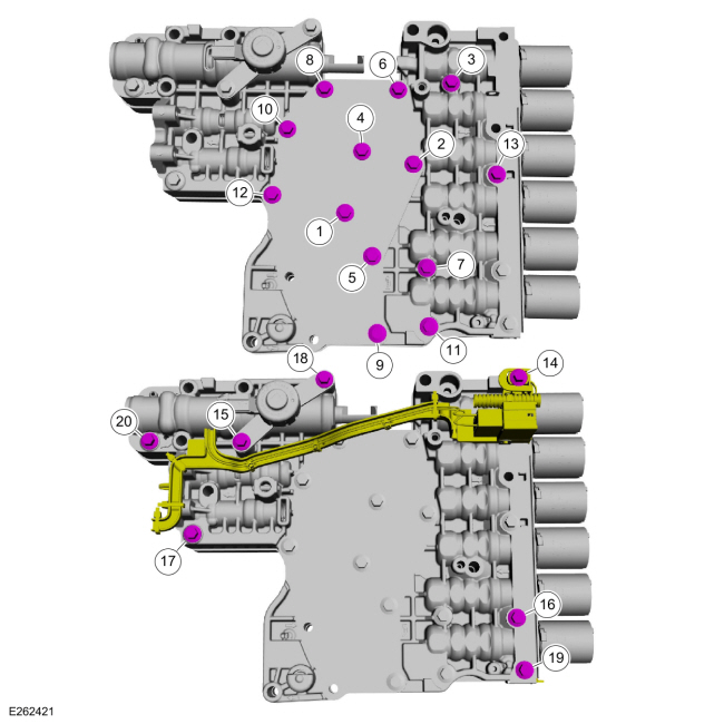
For solenoid and valve identification.
Refer to: Main Control Valve Body (307-01 Automatic Transmission -
10-Speed Automatic Transmission – 10R80, Description and Operation).
-
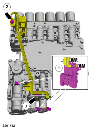
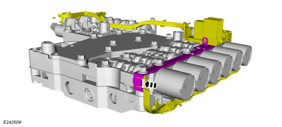
Disconnect the internal wiring harness.
-
Slide the plastic lock to the unlock position. While
pressing the plastic tabs, disconnect the electrical connectors.
-
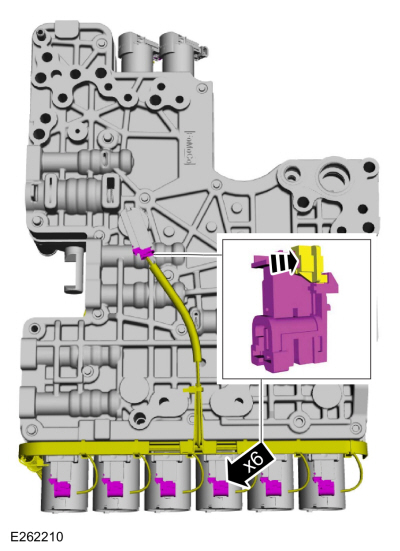
Remove internal wiring harness retaining bolt.
-
Disconnect the internal wiring harness retainer.
-
Disconnect the internal wiring harness electrical connectors.
-
Slide the plastic locks to the unlock position. While
pressing the plastic tabs, disconnect the electrical connectors.
-
Release the retainer and remove the internal wiring harness assembly.
-
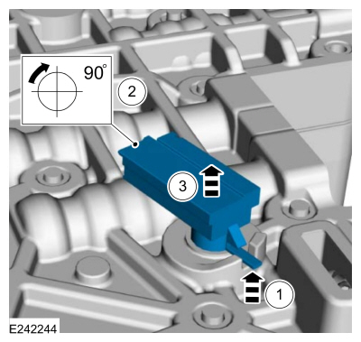
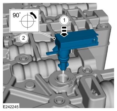
Remove the TFT sensor.
-
Lift plastic tab.
-
Rotate the TFT sensor clockwise.
-
Remove the TFT sensor.
-
Remove the main control assembly to transmission fluid pump seal.
-
NOTE:
The orientation of the solenoids before removal.
-
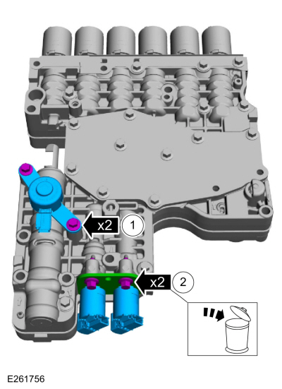
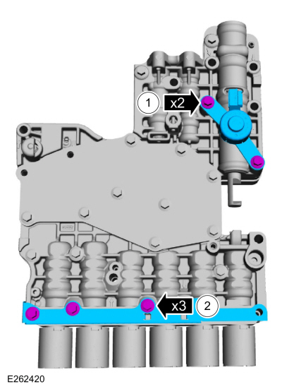
Remove the bolts and the park lock pawl solenoid.
-
Remove and discard the bolts. Remove the solenoid retaining plate, TCC solenoid and the LPC solenoid.
-
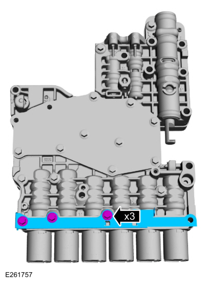
Remove bolts and the shift solenoid retaining plate.
-
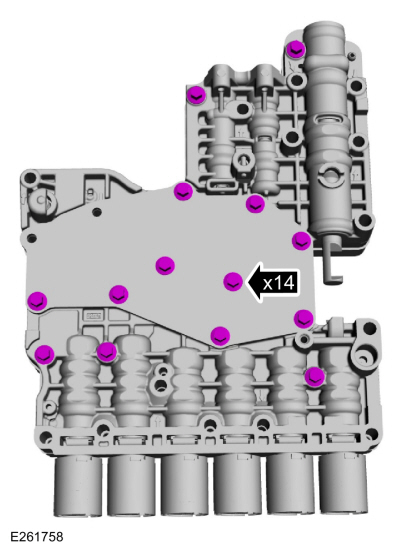
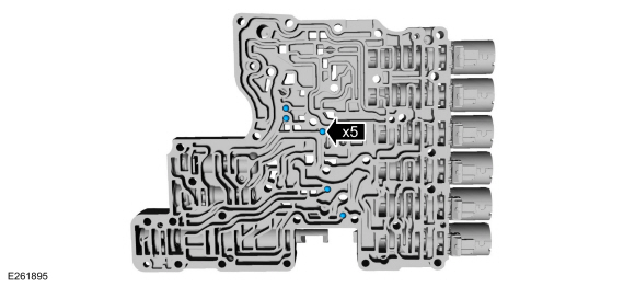
Remove the valve body bolts.
-
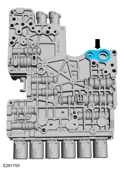
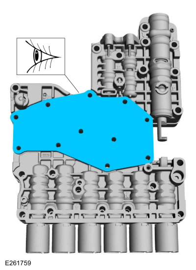
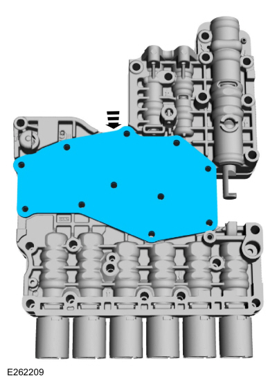
NOTE:
The valve body channel plate can be reused if not damaged.
Remove and inspect the valve body channel plate.
-
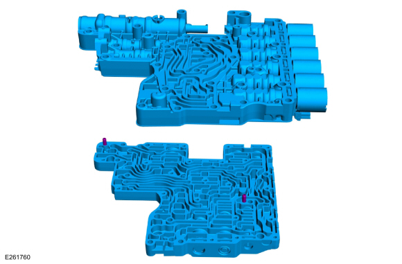
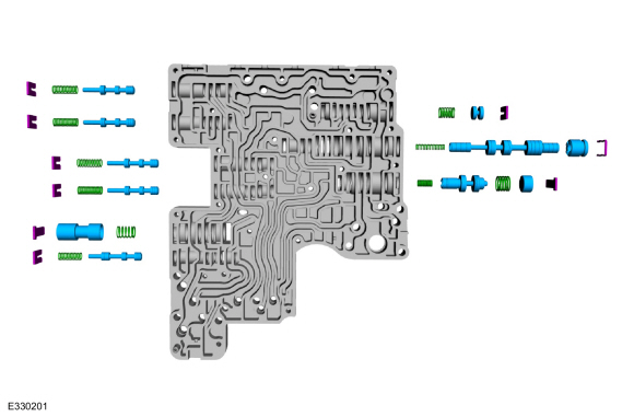
NOTICE:
Many components and surfaces in the main control valve
body are precision machined. Use care when handling the upper and lower
valve body or damage can occur to the machined surfaces.
Separate the upper valve body from the lower valve body.
Lower Valve Body
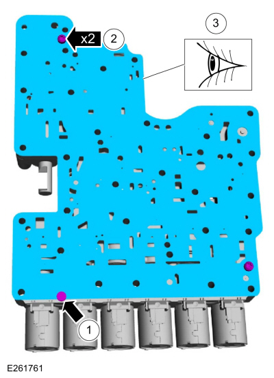
-
NOTE:
The valve body separator plate can be reused if not damaged.
-
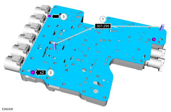
If equipped, remove the pin-type retainer.
-
Remove the valve body separator plate bolts.
-
Remove and inspect the valve body separator plate.
-
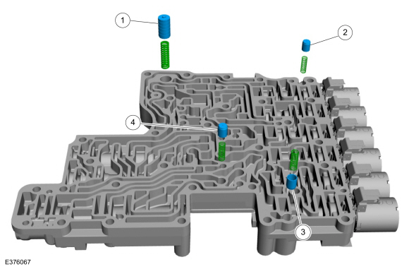
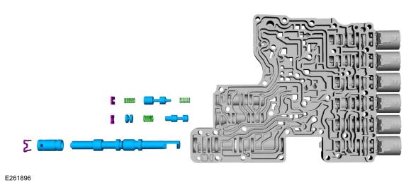
NOTE:
The orientation of the valves and springs.
Remove the following items:
-
LPC damper assembly
-
Clutch exhaust check valve
-
Transmission fluid auxiliary pump check valve
-
Torque converter anti-drainback valve
-
Remove the check balls.
-
NOTICE:
Note the location of the retaining clips, caps,
valves and valve springs for assembly. Failure to install the components
in the correct location will result in harsh/soft or no shifts or
damage to the transmission.
Remove the retaining clips, cap, valves and valve springs from each bore of the valve body assembly.
-
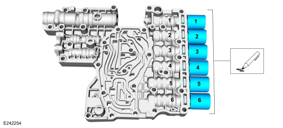
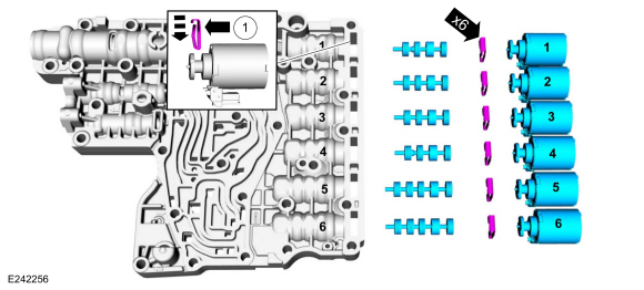
NOTICE:
Solenoids and clutch control valves may visually
appear the same but they are calibrated from the factory and are not all
the same. Use care not to assemble the main control assembly
incorrectly. Incorrect solenoid and clutch control valve installation
results in poor transmission shift quality.
Number the solenoids 1 through 6 and number the main
control solenoid ports 1 through 6 to correspond to the solenoids.
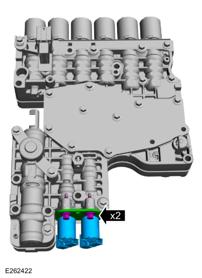
-
NOTE:
Note the location of the clutch control valves and solenoids for assembly.
Remove and discard the shift solenoid retainers. Remove the shift solenoids and clutch control valves.
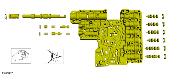
Upper Valve Body
-
NOTICE:
Note the location of the retaining clips, caps,
valves and valve springs for assembly. Failure to install the components
in the correct location will result in harsh/soft or no shifts or
damage to the transmission.
Remove the retaining clips, cap, valves and valve springs from each bore of the valve body assembly.
Upper and Lower Valve Body
-
NOTICE:
Many components and surfaces in the main control
valve body are precision machined. Use care when cleaning the lower
valve body or damage can occur to the machined surfaces.
Clean and inspect the lower valve body for damage.
Inspect the passages and valves for damage and clean any excessive
debris. Install a new component if necessary.
-
Clean and inspect the upper valve body for damage.
Inspect the passages and valves for damage and clean any excessive
debris. Install a new component if necessary.
Upper Valve Body
-
NOTICE:
Failure to install the components in the correct
location will result in harsh/soft or no shifts or damage to the
transmission.
Install the valves, valve springs, caps and the retaining clips into the correct valve body valve bore.
Lower Valve Body
-
NOTICE:
Failure to install the components in the correct
location will result in harsh/soft or no shifts or damage to the
transmission.
Install the valves, valve springs, cap and the retaining clips into the correct valve body valve bore.
-
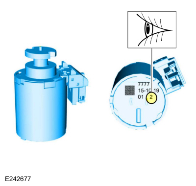
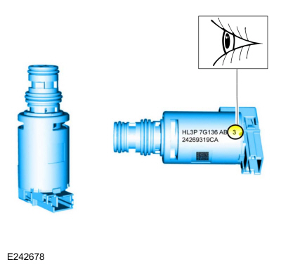
NOTICE:
Solenoids are calibrated from the factory and are
not all the same. To replace a solenoid, match the band number with the
original solenoid or harsh shifts or damage to the transmission can
occur.
If new solenoids are needed, identify the solenoid band number.
-
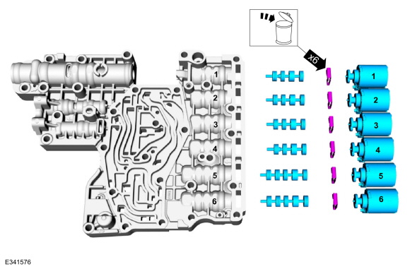
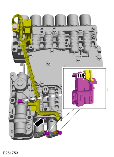
NOTICE:
Failure to install the components in the correct
location will result in harsh/soft or no shifts or damage to the
transmission.
Install the clutch control valves, and the shift
solenoids in the corresponding marked location. Install the new shift
solenoid retainers with the flat side towards the solenoids.
-
Retainer flat side
-
Install the check balls.
-
NOTE:
The orientation of the valves and springs.
Install the following items:
-
LPC damper assembly
-
Clutch exhaust check valve
-
Transmission fluid auxiliary pump check valve
-
Torque converter anti-drainback valve
-
NOTE:
The valve body separator plate can be reused if not damaged.
-
Using the special tools align the valve body separator plate onto the lower valve body.
Use Special Service Tool: 307-299
Alignment Pins, Valve Body.
-
Install the bolts.
Torque:
71 lb.in (8 Nm)
-
If equipped, install the pin-type retainer.
Upper and Lower Valve Body
-
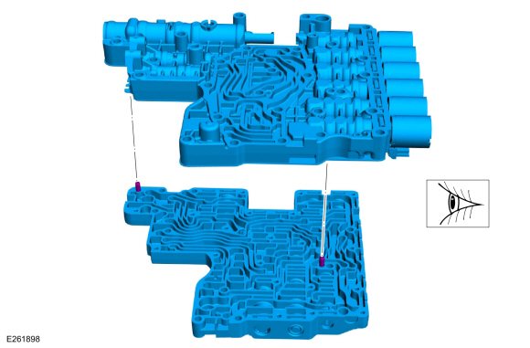
Align the guide pins on the upper valve body with the alignment holes in the lower valve body.
-
NOTE:
The valve body channel plate can be reused if not damaged.
Install the valve body channel plate.
-
Loosely install the valve body bolts.
-
-
Install the park lock pawl solenoid and loosely install the bolts.
-
Install the shift solenoid retaining plate and loosely install the bolts.
-
Tighten the bolts in the sequence shown.
Torque:
106 lb.in (12 Nm)
-
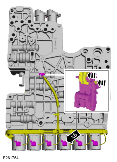
Push the internal wiring harness into the retainer.
-
Install the TFT sensor.
-
Position the TFT sensor in the main control valve body.
-
Rotate the TFT sensor counter clockwise until the plastic tab locks into place.
-
Connect the internal wiring harness electrical connectors.
-
Slide the plastic lock to the locked position.
-
NOTICE:
Solenoids are calibrated from the factory and are
not all the same. To replace a solenoid, match the replacement solenoid
type (normally high/normally low) and the band number with the original
solenoid or harsh shifts or damage to the transmission can occur.
If new solenoids are needed, identify which type
(normally high/normally low) of solenoid it is and the solenoid band
number.
-
-
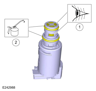
Inspect the solenoid screens for debris that may restrict fluid flow
-
Lubricate the solenoid O-ring seals.
Material: Motorcraft® MERCON® ULV Automatic Transmission Fluid
/ XT-12-QULV
(WSS-M2C949-A, )
(MERCON® ULV)
-
Install the TCC solenoid, LPC solenoid, solenoid retaining plate and the new bolts.
Torque:
80 lb.in (9 Nm)
-
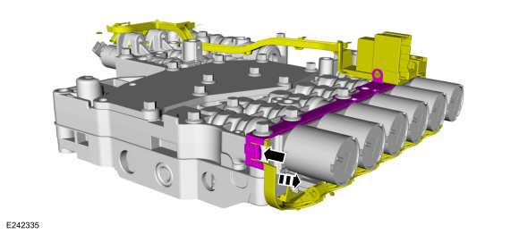
Connect the internal wiring harness.
-
Slide the plastic locks to the locked position.
-
Connect the internal wiring harness retainer.
-
Install the main control assembly to transmission fluid pump seal.
To remove the transmission assembly.
Refer to: Transmission (307-01 Automatic Transmission - 10-Speed Automatic Transmission – 10R80, Removal and Installation)...
Special Tool(s) /
General Equipment
100-001
(T50T-100-A)
Slide Hammer
100-002
(TOOL-4201-C)
Holding Fixture with Dial Indicator Gauge
205-1018Installation Tube
307-003
(T57L-500-B)
Holding Fixture, Transmission
307-091Handle, Torque ConverterTKIT-2009TC-F
307-309Remover, Torque Converter SealTKIT-1994-FMH/FLMHTKIT-1994-..
Other information:
System Operation
Auto Start Stop
The
auto start stop system helps reduce fuel consumption and decrease
emissions by automatically shutting down the engine when the vehicle
stops and the engine is idling, usually within 1500 ms (1.5 seconds). To
initiate the auto start stop operation on automatic transmission
equipped vehicles on automatic transmission equipped vehicles, the
vehi..
Removal
Remove the liftgate trim panel.
Refer to: Liftgate Trim Panel (501-05 Interior Trim and Ornamentation, Removal and Installation).
Disconnect the electrical connectors and the washer hose.
NOTE:
Remove both sides.
Remove the reversing lamp side close out covers.
..

 Transmission. Removal
 Transmission. Overhaul