Lincoln Navigator: Rear Drive Halfshafts / Inner Constant Velocity (CV) Joint Boot. Removal and Installation
Special Tool(s) / General Equipment
| Rubber Mallet | |
| Three Leg Puller | |
| Flat-Bladed Screwdriver |
Materials
| Name | Specification |
|---|---|
| Motorcraft® Constant Velocity Joint Grease XG-5 |
WSS-M1C258-A1 |
Removal
-
Remove the halfshaft.
Refer to: Rear Halfshaft (205-05 Rear Drive Halfshafts, Removal and Installation).
-
-
Remove and discard the large CV boot clamp.
-
Remove and discard the small CV boot clamp.
-
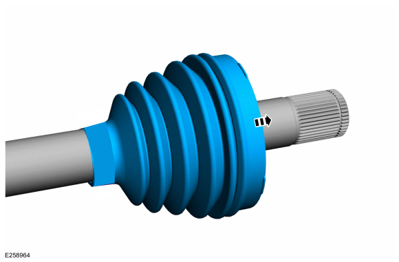
Position the CV boot to access the inner CV housing retaining ring.
-
Remove and discard the large CV boot clamp.
 |
-
Remove and discard the inner CV housing retaining ring.
 |
-
Remove the inner CV joint housing.
 |
-
NOTE: The CV joint cage balls are free to fall out.
Remove and discard the CV joint cage circlip.
 |
-
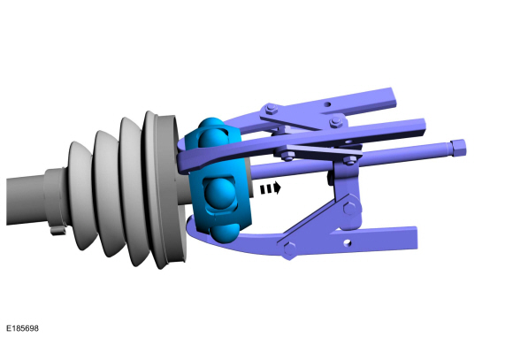
NOTE: The CV joint cage balls are free to fall out.
Using a 3-leg puller, remove the CV joint cage.
Use the General Equipment: Three Leg Puller
 |
-
Remove the CV joint boot.
 |
Installation
-
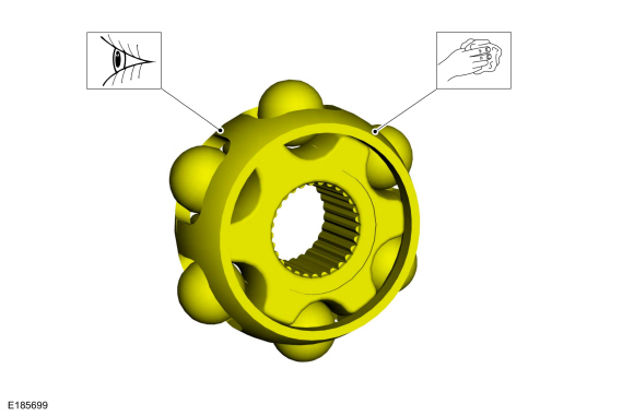
NOTE: CV cage is shown assembled.
Clean and inspect the CV joint cage.
 |
-
NOTE: Make sure that new components are installed.
Install the new CV joint boot.
 |
-
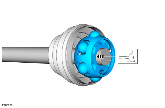
NOTE: The CV joint cage is a snug fit and may need to tapped on with a soft face mallet.
Using a soft face mallet and socket that fit over the shaft and onto the center of the CV joint, install the CV joint cage.
Use the General Equipment: Rubber Mallet
 |
-
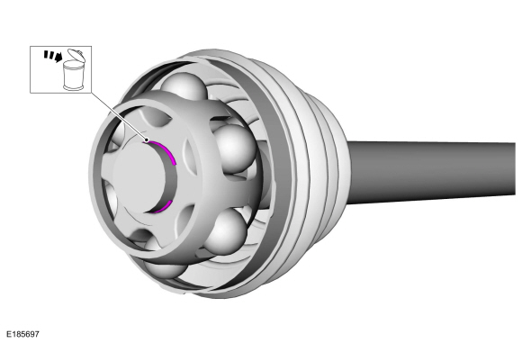
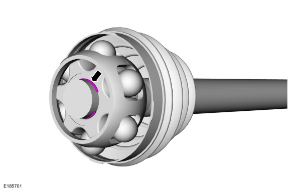
NOTE: Make sure that a new component is installed.
Install the new CV joint cage circlip.
 |
-
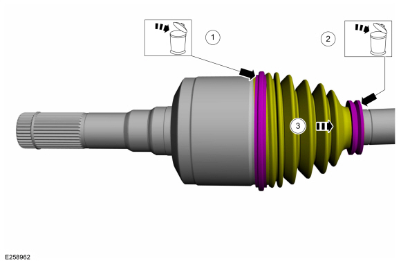
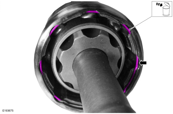
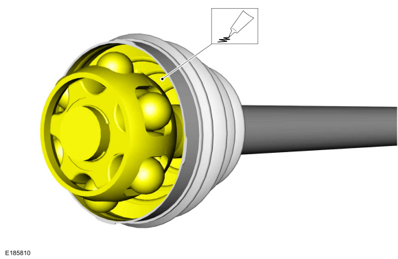
Evenly apply the grease in the CV joint boot and housing.
Material: Motorcraft® Constant Velocity Joint Grease / XG-5 (WSS-M1C258-A1)
 |
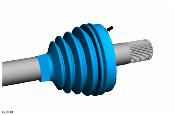
-
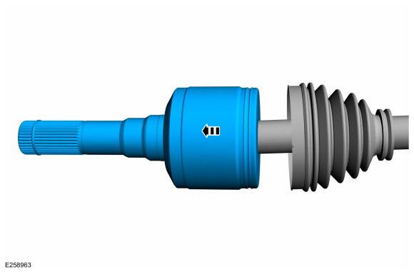
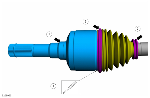
NOTE: When installing the CV joint housing, insert a small flat blade screwdriver under the CV joint boot seat to allow air to escape.
Install the inner CV housing and the new inner CV housing retaining ring.
-
Using a flat blade screw driver to allow air to escape, install the CV joint housing.
Use the General Equipment: Flat-Bladed Screwdriver
-
Install the new small CV joint boot clamp.
-
Using boot clamp pliers, install the new large CV joint boot clamp.
-
Using a flat blade screw driver to allow air to escape, install the CV joint housing.
 |
-
Install the halfshaft.
Refer to: Rear Halfshaft (205-05 Rear Drive Halfshafts, Removal and Installation).
 Rear Drive Halfshafts. Diagnosis and Testing
Preliminary Inspection
Visually inspect the CV joints, housing, boots, and clamps for obvious signs of mechanical damage.
If an obvious cause for an observed or reported concern is
found, correct the cause (if possible) before proceeding to the next
step
If the cause is not visually evident, verify the symptom and REFER to Symptom Chart: NVH...
 Outer Constant Velocity (CV) Joint Boot. Removal and Installation
Special Tool(s) /
General Equipment
Flat Headed Screw Driver
Boot Clamp Pliers
Removal
Remove the inner CV joint boot...
Other information:
Lincoln Navigator 2018-2026 Workshop Manual: Instrument Panel. Removal and Installation
Special Tool(s) / General Equipment Interior Trim Remover Removal NOTE: Removal steps in this procedure may contain installation details. All vehicles Remove both front seats. Refer to: Front Seat (501-10A Front Seats, Removal and Installation)...
Lincoln Navigator 2018-2026 Workshop Manual: Differential Draining and Filling. General Procedures
Draining With the vehicle in NEUTRAL, position it on a hoist. Refer to: Jacking and Lifting (100-02 Jacking and Lifting, Description and Operation). Remove the rear axle fluid drain plug and allow the axle fluid to drain...
Categories
- Manuals Home
- 4th Gen Lincoln Navigator Service Manual (2018 - 2026)
- Body Control Module (BCM). Removal and Installation
- Remote Function Actuator (RFA) Module. Removal and Installation
- Head Up Display (HUD) Module Calibration. General Procedures
- Rear Bumper. Removal and Installation
- Neutral Flat Tow Activation and Deactivation. General Procedures
Front Stabilizer Bar Link. Removal and Installation
Removal
NOTICE: Suspension fasteners are critical parts that affect the performance of vital components and systems. Failure of these fasteners may result in major service expense. Use the same or equivalent parts if replacement is necessary. Do not use a replacement part of lesser quality or substitute design. Tighten fasteners as specified.
NOTE: Removal steps in this procedure may contain installation details.
With the vehicle in NEUTRAL, position it on a hoist.Refer to: Jacking and Lifting (100-02 Jacking and Lifting, Description and Operation).
NOTICE: Do not use power tools to remove or install the stabilizer bar