Lincoln Navigator: Engine Emission Control - 3.5L EcoBoost (272kW/370PS) / Exhaust Gas Recirculation (EGR) Cooler. Removal and Installation
Removal
-
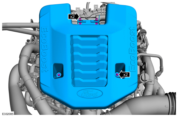
Remove the engine appearance cover retainers, release
the engine appearance cover from the rear retainers and then remove the
engine appearance cover.
-
Remove the RH side air cleaner outlet pipe.
Refer to: Air Cleaner Outlet Pipe RH (303-12 Intake Air Distribution
and Filtering - 3.5L EcoBoost (272kW/370PS), Removal and Installation).
-
Remove the RH side CAC intake pipe.
Refer to: Charge Air Cooler (CAC) Intake Pipe (303-12 Intake Air
Distribution and Filtering - 3.5L EcoBoost (272kW/370PS), Removal and
Installation).
-
Drain the cooling system.
Refer to: Engine Cooling System Draining, Vacuum Filling and Bleeding
(303-03 Engine Cooling - 3.5L EcoBoost (272kW/370PS), General
Procedures).
-
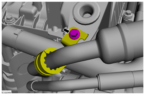
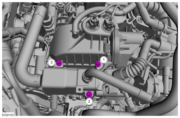
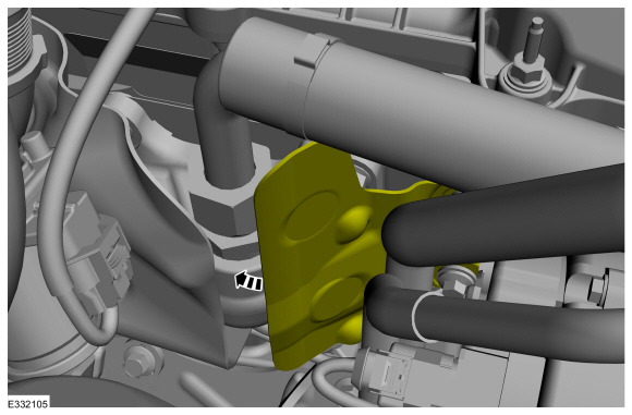
Remove the A/C compressor outlet line bracket retainer and position aside the A/C compressor outline bracket.
-
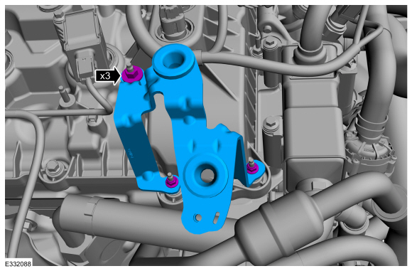
Remove the CAC tube bracket retainers and remove the CAC tube bracket.
-
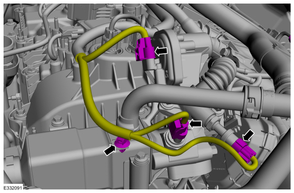
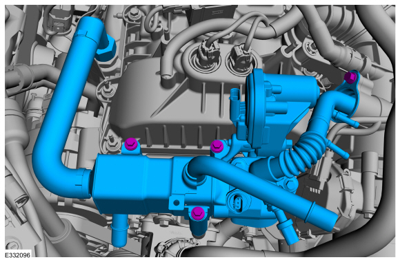
Disconnect the electrical connectors and wiring harness retainer. Position aside the wiring harness.
-
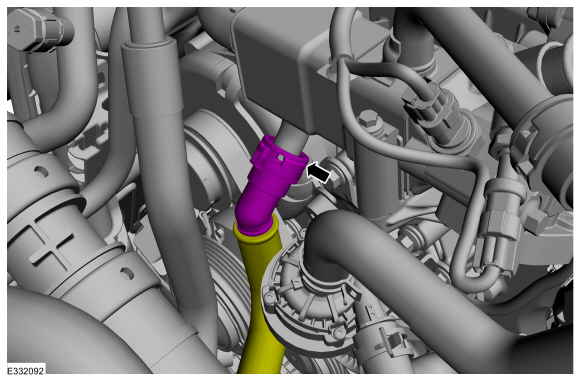
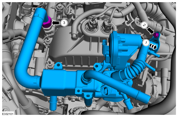
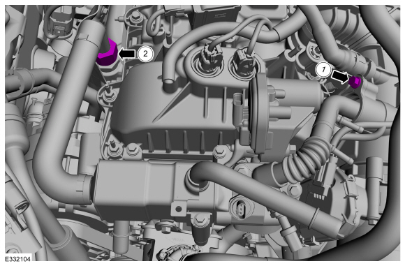
Disconnect the lower coolant hose from the EGR cooler assembly.
Refer to: Quick Release Coupling (310-00 Fuel System - General Information - 3.5L EcoBoost (272kW/370PS), General Procedures).
-
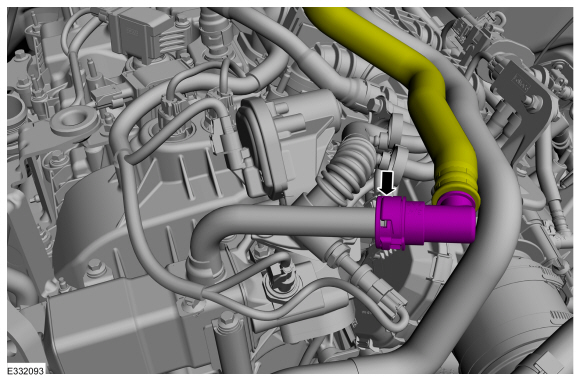
Disconnect the upper coolant hose from the EGR cooler assembly.
Refer to: Quick Release Coupling (310-00 Fuel System - General Information - 3.5L EcoBoost (272kW/370PS), General Procedures).
-
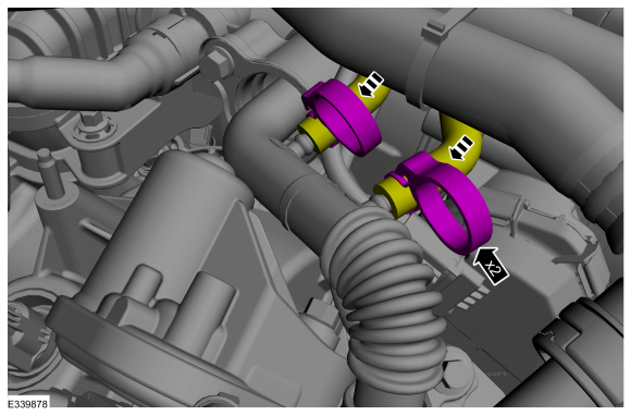
Loosen the clamps and disconnect the differential pressure sensor hoses.
-
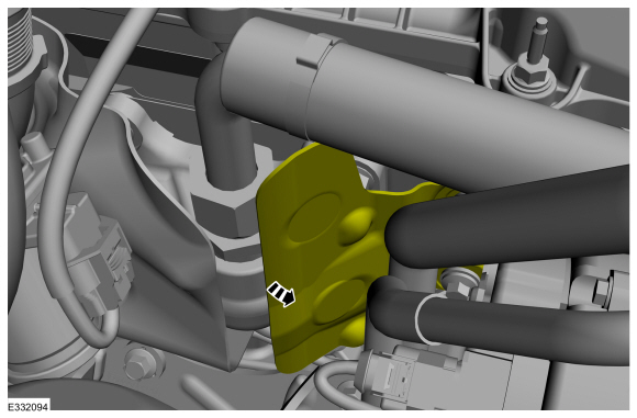
NOTICE:
The exhaust manifold heat shield provides critical
protection for dual generator-equipped engines. If removed, it must be
properly reinstalled.
Position aside the heat shield.
-
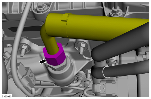
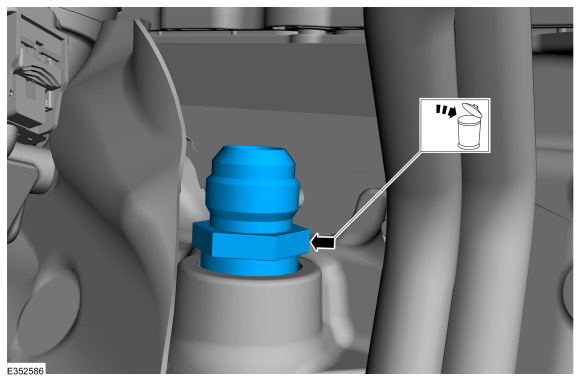
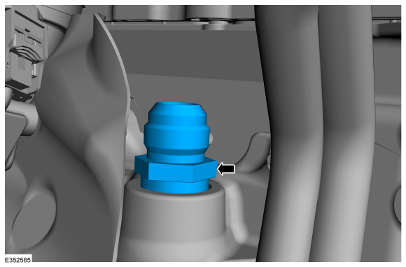
Remove the EGR inlet tube nut.
-
Remove the EGR assembly.
-
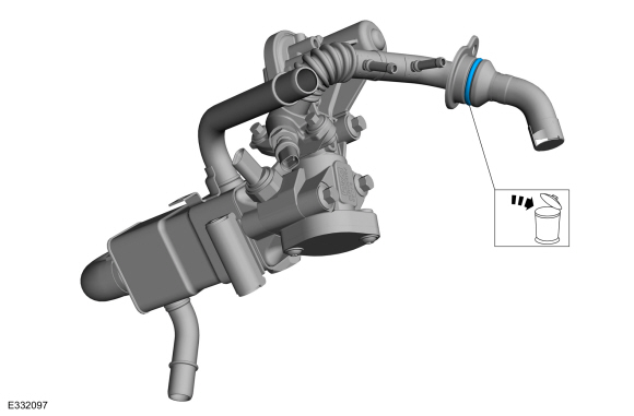
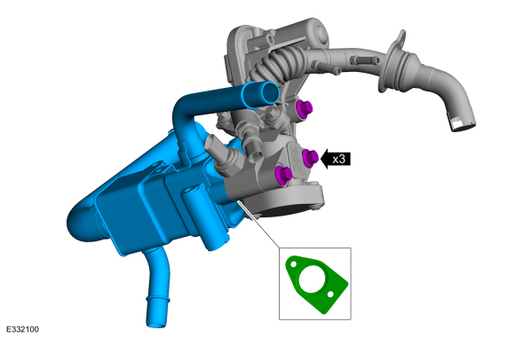
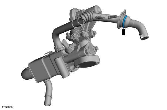
Remove and discard the EGR to exhaust manifold connector.
-
Remove and discard the EGR outlet tube o-ring.
-
-
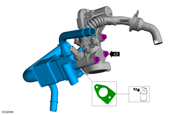
Remove the bolts and EGR cooler assembly.
-
Remove and discard the EGR valve gasket.
Installation
-
-
Install the EGR valve gasket.
-
Install the EGR cooler assembly.
Torque:
22 lb.ft (30 Nm)
-
NOTE:
The new EGR outlet tube O-ring comes with lubricant, no lubricant needs to be applied.
Install the new o-ring.
-
NOTE:
The new EGR to exhaust manifold connector comes with lubricant, no lubricant needs to be applied.
Install the new EGR to exhaust manifold connector.
Torque:
125 lb.ft (170 Nm)
-
-
Install the EGR valve assembly.
-
Install the EGR valve outlet tube fastener and hand tighten at this stage.
-
Install the EGR valve inlet tube nut and hand tighten at this stage.
-
Install the EGR cooler fasteners and hand tighten at this stage.
-
Tighten the EGR cooler fasteners as per the sequence.
Torque:
89 lb.in (10 Nm)
-
-
Tighten the EGR valve outlet tube fastener.
Torque:
89 lb.in (10 Nm)
-
Tighten the EGR valve inlet tube fastener.
Torque:
111 lb.ft (150 Nm)
-
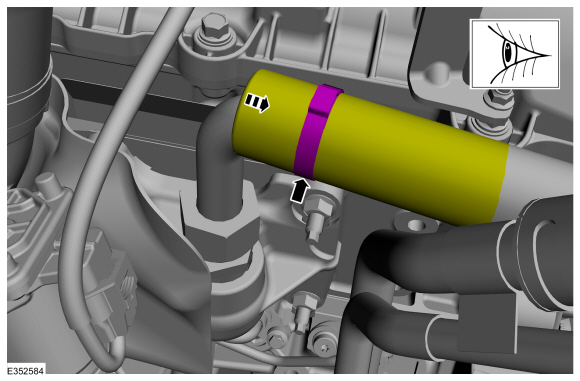
Pull back heat sleeve to visually inspect hot tube for any twisting.
-
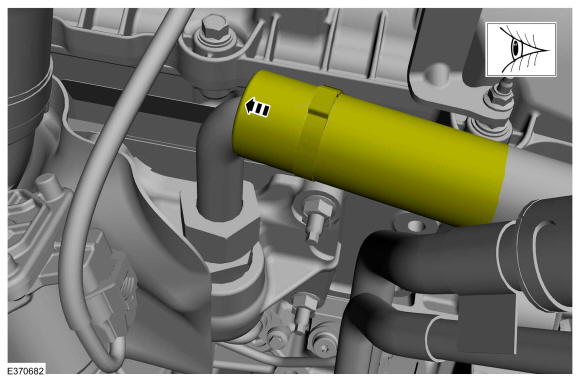
Position back the heat sleeve.
-
Position back the heat shield.
-
Connect the differential pressure sensor hoses.
-
Connect the upper coolant hose to the EGR cooler assembly.
Refer to: Quick Release Coupling (310-00 Fuel System - General Information - 3.5L EcoBoost (272kW/370PS), General Procedures).
-
Connect the lower coolant hose to the EGR cooler assembly.
Refer to: Quick Release Coupling (310-00 Fuel System - General Information - 3.5L EcoBoost (272kW/370PS), General Procedures).
-
Connect the electrical connectors and wiring harness retainer.
-
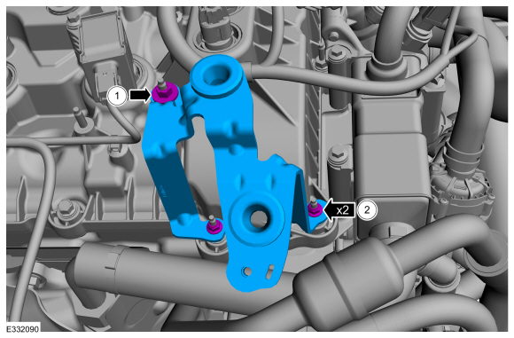
Install the CAC tube bracket and retainers.
Torque:
1:
71 lb.in (8 Nm)
2:
53 lb.in (6 Nm)
-
Position the A/C compressor outlet line bracket and install the A/C compressor outline bracket retainer.
Torque:
106 lb.in (12 Nm)
-
Install the RH side CAC intake pipe.
Refer to: Charge Air Cooler (CAC) Intake Pipe (303-12 Intake Air
Distribution and Filtering - 3.5L EcoBoost (272kW/370PS), Removal and
Installation).
-
Install the RH side air cleaner outlet pipe.
Refer to: Air Cleaner Outlet Pipe RH (303-12 Intake Air Distribution
and Filtering - 3.5L EcoBoost (272kW/370PS), Removal and Installation).
-
Refill the cooling system.
Refer to: Engine Cooling System Draining, Vacuum Filling and Bleeding
(303-03 Engine Cooling - 3.5L EcoBoost (272kW/370PS), General
Procedures).
-
Slide the engine appearance cover into the retaining bracket and install the retainers.
Torque:
97 lb.in (11 Nm)
Removal
NOTE:
Removal steps in this procedure may contain installation details.
Remove the engine appearance cover retainers, release
the engine appearance cover from the rear retainers and then remove the
engine appearance cover...
Removal
Remove the engine appearance cover retainers, release
the engine appearance cover from the rear retainers and then remove the
engine appearance cover...
Other information:
Removal
NOTE:
Removal steps in this procedure may contain installation details.
Remove the front seat backrest.
Refer to: Front Seat Backrest (501-10A Front Seats, Removal and Installation).
Remove the front seatbelt buckle...
Coolant Capacity: Vehicles Built Up To: 08-July-2018
Name
Fill Capacity
Material: Motorcraft® Orange Concentrated Antifreeze/Coolant
/ VC-3-B
(WSS-M97B44-D)
Base radiator — 18...

 Exhaust Gas Recirculation (EGR) Back Pressure Sensor. Removal and Installation
 Exhaust Gas Recirculation (EGR) Outlet Tube. Removal and Installation
 205-1016
 205-153
(T80T-4000-W)
205-153
(T80T-4000-W)
 205-D061
(D83T-4205-C2)
205-D061
(D83T-4205-C2)