
Lincoln Navigator: Rear Disc Brake / Brake Caliper Anchor Plate. Removal and Installation
Removal
NOTE: Removal steps in this procedure may contain installation details.
-
Remove the brake pads.
Refer to: Brake Pads (206-04 Rear Disc Brake, Removal and Installation).
-
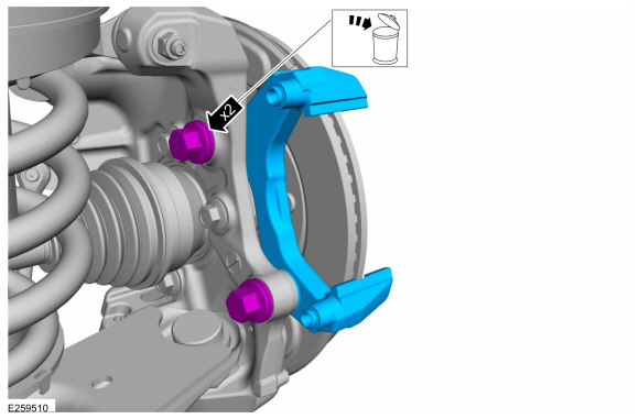
Remove the bolts and the anchor plate. Discard the bolts
Torque: 258 lb.ft (350 Nm)
 |
Installation
-
To install, reverse the removal procedure.
 Brake Caliper. Removal and Installation
Removal
NOTICE:
Make sure that all openings are sealed.
NOTICE:
If the fluid is spilled on the paintwork, the affected area must be immediately washed down with cold water...
 Brake Disc. Removal and Installation
Materials
Name
Specification
Motorcraft® Metal Brake Parts CleanerPM-4-A, PM-4-B, APM-4-C
-
Removal
NOTE:
Removal steps in this procedure may contain installation details...
Other information:
Lincoln Navigator 2018-2026 Workshop Manual: Specifications
General Specifications Item Specification Spark plug 12405 Spark plug gap 0.030 in ( .75 mm) ..
Lincoln Navigator 2018-2026 Workshop Manual: Interior Camera System - System Operation and Component Description. Description and Operation
System Operation System Operation Overview The interior camera system works with the active drive assist system to continuously observe the driver when the active drive assist system is in use. The interior camera system observes the drivers eyes and head position to determine if the driver is attentive or distracted. The interior camera system consists of: Driver sid..
Categories
- Manuals Home
- 4th Gen Lincoln Navigator Service Manual (2018 - 2026)
- Front Bumper Cover. Removal and Installation
- Power Running Board (PRB). Diagnosis and Testing
- Liftgate Trim Panel. Removal and Installation
- Body Control Module (BCM). Removal and Installation
- Head Up Display (HUD) Module Calibration. General Procedures
Rear Drive Halfshafts. Diagnosis and Testing
Preliminary Inspection
Visually inspect the CV joints, housing, boots, and clamps for obvious signs of mechanical damage.If an obvious cause for an observed or reported concern is found, correct the cause (if possible) before proceeding to the next step
If the cause is not visually evident, verify the symptom and REFER to Symptom Chart: NVH.
